Download
1 / 27
270 likes | 465 Views
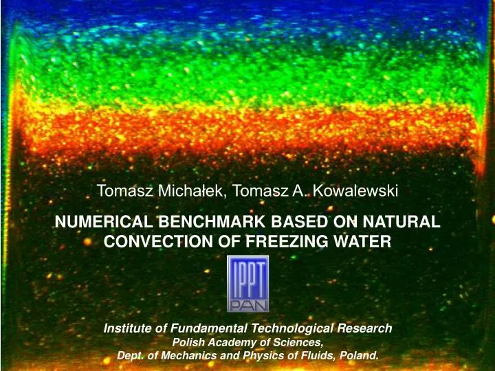
Tomasz Michałek, Tomasz A. Kowalewski. NUMERICAL BENCHMARK BASED ON NATURAL CONVECTION OF FREEZING WATER. Institute of Fundamental Technological Research Polish Academy of Sciences, Dept. of Mechanics and Physics of Fluids, Poland. Building confidence to CFD results. Verification.

E N D
Tomasz Michałek, Tomasz A. Kowalewski NUMERICAL BENCHMARK BASED ON NATURAL CONVECTION OF FREEZING WATER Institute of Fundamental Technological Research Polish Academy of Sciences, Dept. of Mechanics and Physics of Fluids, Poland.
Building confidence to CFD results Verification Validation Code/Program verification Verification of Calculation Validation of Idealized problems Validation of actual configuration • Method of • manufactured solution [Roache] • Analytical solutions • Numerical benchmarks • [Ghia, de Vahl Davis, • Le Quere,…] • Unit problems • Benchmark cases • Simplified/Partial • Flow Path • Actual Hardware • [Sindir et al.] • Richardson extrapolation (RE) • Generalized RE • [Stern at all.] • Grid Convergence Index (GCI) [Roache] sensitivity analysis
BENCHMARK DEFINITION FOR THERMAL AND VISCOUS FLOWS • 2D viscous, incompressible flow driven by natural convection • Navier – Stokes equations with non-linear buoyancy term (water) coupled with heat transfer • Temperature gradient ΔT = 10ºC • Verified programs: Th = 10C Tc = 0C • FRECON (FDM) • FLUENT (FVM) • FIDAP (FEM) • SOLVSTR (FDM) • SOLVMEF (MEF) Ra = 1.5 · 106 Pr = 13.31
VERIFICATION PROCEDURE CALCULATE: SOLUTION S , SOLUTION UNCERTAINTY USN Error indicator for code comparisons Reference solution
INTER-CODE COMPARISONS FRECON3V (FRE) FLUENT 6.1. (FLU) FIDAP 8.7.0.(FID) SOLVSTR (STR) Details of the reference solutions w(x) Michalek T., Kowalewski T.A., Sarler B. ”Natural Convection for Anomalous Density Variation of Water:Numerical Benchmark” Progress in Computational Fluid Dynamics, 5 (3-5),pp 158-170,2005 U,W along Y=0.5L U,W along X=0.5L U,W along X=0.9L
SENSITIVITY ANALYSIS COMP. RESULTS INITIAL PARAMETERS Boundary conditions TH, TC, Text, Q1, Q2, Q3 Initial conditions Tinit. ,vinit Material properties ,,,,cp MODEL OUTPUT SENSITIVITY MEASURES 1. Fundamental parameters for validation procedure 2. Precision of measurements necessary to validate calculations
CAVITY T14 PLEXIGLASS WALL T7 T10 Th Tc ALUMINIUM WALL ALUMINIUM WALL TL TP PLEXIGLASS WALL T15 CENTRAL CROS-SECTION TE1 TE2
MEASUREMENTS TECHNIQUES • Particle Image Velocimetry • Particle Image Thermometry • 2D Visualization • Point temperature measurements correlation F(t0) F(t0+t)
ESTIMATION OF EXP. UNCERAINTY UD • PIV Avg. Fields N – length of series Std. Dev. Std. Dev. Error Experimental Data Uncertainty • PIT
EXPERIMENTAL BENCHMARKTwo Liquid Crystals cover entire color range [0 C, 10 C] PIT Ra = 1.5*106 Pr = 11.78 Th = 10 C Tc = 0 C PIV
EXPERIMENTAL BENCHMARK 2D Temp. Field Temp. along X = 0.9L Temp. along Y = 0.5L W along Y = 0.5L U along X = 0.5L W along X = 0.9L
EXPERIMENTAL UNCERTAINTY ESTIMATION N = 40, t = 1s • PIV • PIT
VALIDATION METHODOLOGY Stern et all., Comprehensive approach to verification and validation of CFD simulations – Part 1: Methodology and procedures Journal of Fluids Engineering – Transactions of ASME, 123 (4), pp. 793-802,2001. • Comparison Error • Validation metric In our example: for water
VALIDATION EXAMPLE Simulation A variable material properties of water ,,cp Simulation B const. material properties of water ,,cp = const. Simulation C Adiabatic and isothermal walls Temperature fields Velocity Fields
THERMAL BOUNDARY CONDITION VALIDATION Computational Simulation Tc= - 2C Th=10C Experiment
THERMAL BOUNDARY CONDITION VALIDATION Computational Simulation Tc = -1C Th=10C Experiment
THERMAL BOUNDARY CONDITION VALIDATION Computational Simulation Tc=1C Th=10C Experiment
THERMAL BOUNDARY CONDITION VALIDATION Computational Simulation Tc=2C Th=10C Experiment
VALIDATION – QUANTITATIVE COMPARISONS Y=0.5L X=0.5L X=0.9L Temperature profiles Velocity profiles
NATURAL CONVECTIVE FLOW FOR HIGH RAYLEIGH NUMBERS Th = 27.33 C Tc = 6.87 C Th = 27.21 C Tc = 6.77 C
NATURAL CONVECTIVE FLOW FOR HIGH RAYLEIGH NUMBERS Ra = 3x10⁷ Ra = 4.4x10⁸
NATURAL CONVECTIVE FLOW FOR HIGH RAYLEIGH NUMBERS Ra = 3x10⁷ Ra = 1.5x10⁸ Turbulence Intensity Ra = 1.8x10⁸ Ra = 4.4x10⁸ N = 150 t = 100 ms t = 15 sec
NATURAL CONVECTIVE FLOW FOR HIGH RAYLEIGH NUMBERS Ra = 3x10⁷ N=150 t = 100 ms
NATURAL CONVECTIVE FLOW FOR HIGH RAYLEIGH NUMBERS Ra = 4.4x10⁸ N=138 t = 100 ms
CONCLUSIONS Numerical benchmark based on natural convection of freezing water was defined A method based on sensitivity analysis for the sake of initial parameters was devised for identification of fundamental (crucial) parameters and determination of necessary measurement’s precision needed in validation procedure. Experimental benchmark was defined for proposed configuration 2D Temperature field, 2D Velocity field, was obtained for defined configuration Uncertainty of experimental data were assessed Validation procedure for computational calculations was performed in order to quantitatively assess assumed modeling errors.