Download
1 / 21
210 likes | 343 Views
Hybrid QD0 Studies. M. Modena CERN. Acknowledgments: CERN TE-MSC CLIC Magnets Study Team: A.Aloev , E. Solodko, P.Thonet , A.Vorozhtsov. “CLIC/ILC QD0” Meeting 23 October 2013. Outline:. CLIC QD0 status A hybrid QD0 for ILC ? (basic conceptual design). 2. 3.

E N D
Hybrid QD0 Studies M. Modena CERN Acknowledgments: CERN TE-MSC CLIC Magnets Study Team: A.Aloev, E. Solodko, P.Thonet, A.Vorozhtsov “CLIC/ILC QD0” Meeting 23 October 2013
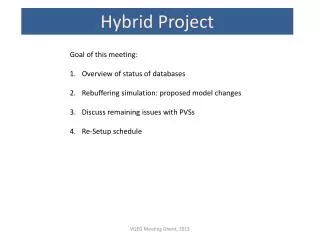
Outline: CLIC QD0 status A hybrid QD0 for ILC ? (basic conceptual design) 2
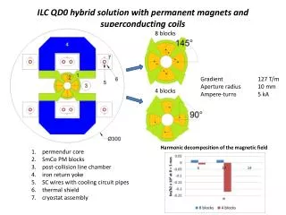
3 CLIC QDO ( 3 TeV; L*=3.5 m) typical layout
CLiC QD0 Status A shortQD0 prototype (for CLiC 3TeV layout) was built at CERN in 2010-2011. Objective: validate the Hybrid Magnet design proposed: PM blocks - Permendur core structure - coils for tunability(low current density). Twocampaign of measurements were done in 2012 in two different configuration: QD0 equipped with Nd2Fe14Bblocks (measured in January 2012) QD0 equipped with Sm2Co17 blocks (measured in August 2012). “Vibrating Wire” MM method was used (the only available due to the small magnet radius). 5
CLiC QD0 Status COMPUTED Gradient (blue curves) and MEASUREDGradient(red dots) (extrapolated from the INTEGRATEDGRADIENT effectively measured), with Sm2Co17blocks (on the left: 504 T/m) and Nd2Fe14B blocks (on the right : 514 T/m). • Sm2Co17 blocks: very good agreement with the FEA computation. • Nd2Fe14B blocks: a difference of ~ -6% is visible. • We suspect something not conform in the NdFeB blocks. • This will be investigate in the next months (waiting a magnetic measurements Helmholtz coils system delivery).
CLiC QD0 Status Prototype FIELD QUALITY (given as magnetic harmonic content, multipoles) versus the magnet powering: Nd2Fe14B (upper graph), Sm2Co17 (lover graph). NOTE: the first “permitted” mutipole is b6: at NI=5000A we compute b6=1.4 units (NdFeB) and b6=0.7 units (SmCo). 7
Field quality tuning: ex. SD0 Opt.1 S-grad 222 020 T/m2 Opt.2 S-grad 220 349 T/m2 Opt.3 S-grad 221 247 T/m2 Opt.4 S-grad 215 785 T/m2 8
Outline: CLIC QD0 status A hybrid QD0 for ILC ? (basic conceptual design) 9
A hybrid QD0 for ILC ? Basic ILC QD0 parameters (R.Tomas Garcia: private communication, 8 May 2013):- Crossing angle: 14 mrad- L* = 3.5 m- QD0 full aperture: 2 cm- QD0 total length: 2.2 m- QD0 gradient: 124 T/m- Post Collision Line vacuum pipe radius at 3.5 m: ~ 12.5 mm 12
A hybrid QD0 for ILC ? Examples of the optimization done on 3 parameters (αin, αout, ↑easy dir;) (R out=30 mm).The sets of values that maximize field quality are 32° for both αin, αout, and 55° for the easy dir. (1st Table) αin αout PM “Easy direction” Rout 13
A hybrid QD0 for ILC ? We have tried to “scale” our QD0 design taking into account the geometric condition but also starting an optimization of the main parameter toward a wider field quality range for the asked tunability.(thanks to A. Aloev for the FEA calculation!). “red line” inside the aperture: area where ΔG/G ≤1 unit (good field region) Main multipoles estimation at r = 3 mm; 5000 NI is the nominal working point (G:125 T/m) 14
A hybrid QD0 for ILC ? In this slide the MAXIMUM GRADIENT configuration (~ 142 T/m )Poles are wider, saturation appear in some areas, field quality is deeply affected (even in these IDEAL CALCULATION To not forget! ) “red line” inside the aperture: area where ΔG/G ≤1 unit (good field region) 15
A hybrid QD0 for ILC ? A basic sketch for the hybrid QD0 adapted to the ILC parameters:- As for CLIC case, this solution minimize vibrations.- Coils are sized to a current density of J ~ 0.9 A/mm ( no water cooling).- Overall dimension are in the range of 500 x 500 mm. Other solutions , for ex. minimizing the cross-section, could be studied. In that case some coils cooling system will be necessary. 16
Some conclusions: • CLIC QD0 baseline (for L*=3.5 m) is an hybrid quadrupole design. • A short prototype of the magnet was successfully built to validate the concept. • We have recently started a hybrid magnet design study for the ILC (i.e. CLIC QD0 design scaled to ILC geometry and strength) • Field quality aspects are also take into account in the study, that shows possible optimization paths for the magnet performances. • In order to proceed with the study, we should discuss and have inputs about boundary conditions imposed by the ILC experimentsand accelerator . • Among them: a. QD0 cross-section limitation b. tunability required c. field quality requirements d. vibrations limitation requirements • The study for an anti-solenoid system should be also evaluated. Thanks 17
Extra slides 18
CLiC SD0 Status Main requirements & boundary conditions: - Tunability of ~ -20 % Minimized vibrations (magnet should be actively stabilized) Integration with the Post Collision vacuum pipe needed. Compactness is less critical respect to QD0. Magnet is placed outside the Detector onthe Accelerator Tunnel border. Prototype key aspects: - The proposed design should permit us to investigate the very precise assembly of several (4 or 5) longitudinal sections, each equipped with PM. Manufacturing (with highest precision) of each Permendur sector, PM insert, “C” shape return yokes Measuring, Assembly and sorting of PM blocks Assembly of the sectors (magnetic forces between blocks impact? PM blocks are very fragile!) Magnetic measurements Final alignment Ø 850 mm 19
The “Single Stretched Wire”,“Vibrating Wire” and “oscillating wire” MM Systems 20