Download
1 / 30
300 likes | 486 Views
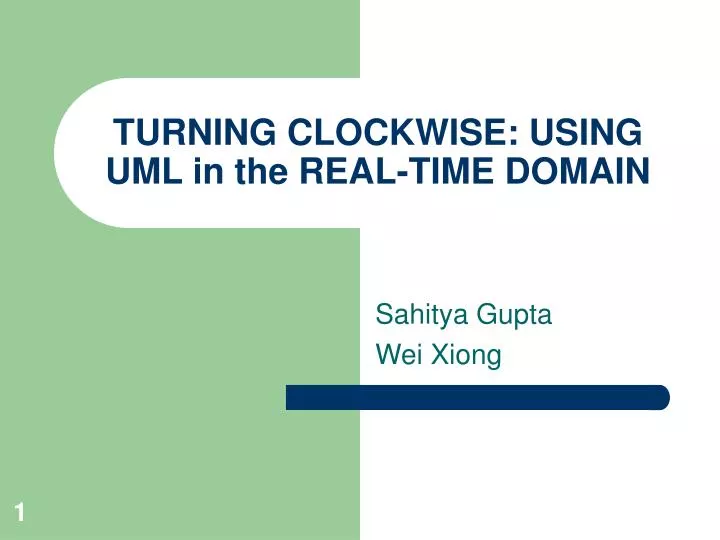
TURNING CLOCKWISE: USING UML in the REAL-TIME DOMAIN. Sahitya Gupta Wei Xiong. Introduction. Physical world is the root cause of the complexity of real-time systems. Persistent demand for always increasing functionality. Solution:

E N D
TURNING CLOCKWISE: USING UML in the REAL-TIME DOMAIN Sahitya Gupta Wei Xiong
Introduction • Physical world is the root cause of the complexity of real-time systems. • Persistent demand for always increasing functionality. • Solution: Modeling. It is simply a form of abstraction that facilitates both problem understanding and problem resolution. FOR MORE INFO...
Real-Time Systems and Object Paradigm • A real time system is a software system that maintains an ongoing and timely interaction with its environment. • In real time systems the dominant feature is the system itself and not its behavior which is changing continuously. This makes it a perfect fit for an object-oriented model. • Misconceptions of object technology have been reduced or eliminated FOR MORE INFO...
Requirements for Modeling Real-Time Systems Some of the requirements in the real-time systems are deriving accurate predictions of key attributes of actual system like response time, throughput, availability, computing delays and resources as statistical quantities, need to model engineering infrastructure, structure and behavior of software. They are classified as Infrastructure modeling requirements, Behavior modeling requirements and Structure modeling requirements. • Infrastructure modeling requirements. This set of requirements include representing resources by its attributes so as to analyze and make predictions about the system depending on the attributes values. Also individual memory and processing requirements of objects in a system are necessary for performance modeling. FOR MORE INFO...
Requirements for Modeling Real-Time Systems (Cont’d) Behavior modeling requirements. Unpredictability and Concurrency of real-world event leads to an event-driven (suitable for modeling discrete behaviors in which concurrent events occur asynchronously) and time-driven (suitable for continuous or periodic inputs) styles to specify behavior of the system instead of the sequential paradigm used for procedural programming. Structure modeling requirements. There is a need formodeling complex high-level runtime structures as well as dynamic runtime structures (in which objects and links are continuously being created and destroyed) in a real-time system. FOR MORE INFO...
Background (UML) • The Unified Modeling Language is a third-generation method for specifying, visualizing, and documenting the artifacts of an object-oriented system under development. • It can be used with many processes, throughout the development life cycle, and across different implementation technologies. FOR MORE INFO...
Background (UML Diagrams) Static Views • Use Case Diagrams • Class Diagrams • Object Diagrams • Component Diagrams • Deployment Diagrams FOR MORE INFO...
Use Case Diagrams Box Office Buy subscription Clerk Buy tickets Actor Kiosk Actor Survey sales Use case Supervisor System FOR MORE INFO...
Class Diagram Association (1:1, 1:*) Class Name Customer Reservation Name: String Phone: String 1 Attributes… Date: Date * purchased owner add(name,phone) Methods… Rolenames Association Class Class FOR MORE INFO...
Component Diagram CreditCardCharges interfaces Component Usage dependency Charge CreditCardCharges Component FOR MORE INFO...
Background (UML Diagrams) Dynamic Views • Sequence Diagrams • Collaboration Diagrams • Activity Diagrams • State-chart Diagrams FOR MORE INFO...
Sequence Diagram Object Object Object Request(query) Reply(result) Request(query) Reply(result) messages Request(query) Request(query) Reply(result) Lifeline (active) Reply(result) FOR MORE INFO...
Collaboration Diagram kiosk Active Object 1: request(count, performance) 4: offer(seat-list) link messages 5: buy(seats) 8: confirm(seats, cost) Object ticketSeller messages Object FOR MORE INFO...
Using UML for Modeling Real-Time Systems UML is a general-purpose modeling language that provides an extensive conceptual base for broad spectrum of application domains. Real-time modeling can be fully accommodated by specializing appropriate base concepts. Any practitioner with general UML background will be able to understand a model based on specializations even without knowledge of added semantics. FOR MORE INFO...
Modeling the Engineering Infrastructure Modeling resources and system services • Most resources can be modeled by appropriate stereotypes of the general UML concepts of classifier or class • Each resource provides some type of specialized functionality required by the logical elements that it supports • A resource may support one or more elements of a logical model while a model element may require the support of multiple resources Element-to-resource mapping • A real-time system is frequently designed to run on different hardware configuration • It is convenient to combine a mutually consistent set of element-to-resource mappings of a given logical model into a single package, called resource-mapping package which relates a logical model to a particular hardware configuration FOR MORE INFO...
Modeling the Engineering Infrastructure (cont’) Resource-to-value mapping • The association of resource attribute values (processor speeds, queue sizes) to the resources is called resource value package • This is required for quantitative analysis of a model Modeling time and timing facilities • A base type, Time, is defined in the standard of UML, but its semantics are not specified so that applications are free to define different models and representations of time • All timing facilities, suck as clocks, calendars, and timing services can be modeled directly as resources. • A time-driven behavior may cause an event-driven behavior FOR MORE INFO...
Modeling Real-Time Behavior The fundamental notion of concurrency is modeled using the “active” object concept of UML due to the fact that different situations may be resolved very differently and no single approach can satisfy all possible real-time applications An active object is an object that owns a thread of control and may initiate control activity. A passive object is one that holds data but that does not initiate control. Processes and tasks are traditional kinds of active objects. • Event-driven (reactive) behavior modeling • Time-driven behavior modeling • Object interaction modeling FOR MORE INFO...
Event-driven (Reactive) Behavior Modeling The underlying model is of an entity that performs a transition from one quiescent state to another in reaction to the arrival of an event Reset/ Uninitialized ReadyToSend A ackB/ Send/A Data/ Reset/ Data/ SendingA SendingB Initialized Error SendingB Stop/ Start/ ReadyToSendB Operational ackA/ Error/ Control behavior Functional behavior FOR MORE INFO...
Event-driven (Reactive) Behavior Modeling A problem Two different state machines that describe different aspects of the behavior of the same object may cause problems Solution • Compose the two state machines by combining them in two peer concurrent states • Use hierarchical states FOR MORE INFO...
Time-Driven Behavior Modeling • Time-driven behavior is based on periodic activities, it is not suitable for modeling using the object paradigm • But control activities are inherently event-driven (the occurrence of failures, the arrival of operational data, etc.) Even in case of time-driven behavior, it is appropriate to use state machines at the highest level of description of an object • Time-driven can converts to event-driven FOR MORE INFO...
Object Interaction Modeling • It is useful to specify and view the emergent behavior of a set of collaborating objects • The UML provides a number of facilities for this purpose: sequence diagrams protocols interaction diagrams activity diagrams FOR MORE INFO...
Protocol • A protocol specifies a set of valid behaviors (signal exchanges) between two or more collaborating objects. • To make such a dynamic pattern reusable, protocols are de-coupled from a particular context of collaborating object and are defined instead in terms of abstract entities called protocol roles. A protocol role represents the activities of one participant a protocol. It is defined by a set of incoming signals, a set of outgoing signals, and optional behavior specification. • Protocols are reusable. FOR MORE INFO...
Modeling Real-Time Structure • Runtime structures represent the architectural core of a real-time system. • A well-designed architecture will allow a system to easily accommodate evolutionary growth and prolong its useful lifetime • UML applies collaboration diagrams for specifying architectures FOR MORE INFO...
Architectural Modeling The central idea is to capture architectural specifications in a formal way Advantages • Architectural models can be formally analyzed for consistency and completeness • The models are executable and allow early and precise assessment of the validity of different architectural approaches • Allows implementations to be derived directly from architectural specifications using automatic code generation UML collaboration diagrams are applied for specifying complex real-time architectures FOR MORE INFO...
Capsule, Port and Connector Ports Connector Capsule The central architectural entity is capsule. Capsule are complex, potentially concurrent, and possibly distributed active architectural components. A port is a physical part of the implementation of a capsule that mediates the interaction of the capsule with the outside world. It is an object that implements a specific interface. Connectors capture the key communication relationships between capsules. FOR MORE INFO...
Collaboration and Roles • To understand the mechanisms used in a design, it is important to see only the objects and the messages involved in accomplishing a purpose or a related set of purposes. A collaboration is a set of participants and relationships that are meaningful for a given set of purposes. • A collaboration is shown as a graph of class references and association references. Each reference is a role of the collaboration; that is, each entity is playing a role within the context of the collaboration, a role that is only part of its full description. • The names of the objects represent their roles within the collaboration. A collaboration is a prototype; in each use of the collaboration the roles are bound to actual objects. FOR MORE INFO...
Collaboration Diagram Collaboration diagrams represents a collaboration, which is a set of objects related in a particular context, and an Interaction, which is a set of messages exchanged among the objects within a collaboration to effect a desired operation or result. FOR MORE INFO...
Strengths • This paper highlights that UML, which is a common industry standard, can be easily adopted and used to model a real-time system thus eliminating a need of learning and using a new tool or language. FOR MORE INFO...
Weaknesses • Does not convey the scope and limitations of UML with respect to embedded systems. FOR MORE INFO...
Relevance to Embedded Software Currently modeling is one of the key issues in the development of any system including an embedded system. It plays a key role in the overall system design. A perfectly modeled system leads to lesser discrepancies in the developed system. FOR MORE INFO...