Download
1 / 20
200 likes | 379 Views
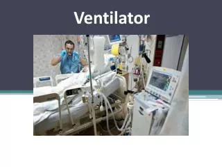
Add-on Mixing Chamber for Mechanical Ventilator. March 5, 2004. Team Members Missy Haehn (BWIG) Laura Sheehan (BSAC) Ben Sprague (Communications) Andrea Zelisko (Team Leader) Client Matt O’Brien, RPT Advisor Professor John Webster. Problem Statement.

E N D
Add-on Mixing Chamber for Mechanical Ventilator March 5, 2004
Team Members • Missy Haehn (BWIG) • Laura Sheehan (BSAC) • Ben Sprague (Communications) • Andrea Zelisko (Team Leader) • Client • Matt O’Brien, RPT • Advisor • Professor John Webster
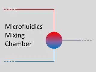
Problem Statement To develop a mixing chamber to help stabilize oxygen percentage delivered from mechanical ventilators to critically ill patients; this chamber would allow for increased accuracy of metabolic measurements.
Background • Critically-ill patients on mechanical ventilators have higher metabolic rates than healthy individuals • This higher rate leads to changes in caloric needs in the patient diet • The patient’s caloric intake must be precise in order to prevent malnutrition and because it affects CO2 production which can deteriorate respiratory muscles and lead to difficulty in weaning off the ventilator
Background cont. • Indirect calorimetry is a method of metabolic measurement used to determine the nutritional needs of a patient • Method utilizes the Respiratory Quotient (RQ) which is the CO2 produced divided by the O2 consumed • RQ determines if patient is being over or underfed carbohydrates, lipids, proteins, etc. • Breath-by-breath measurements are made using a pneumotach to measure flow and a gas sample line to measure concentration of the gas mixture
Motivation • Client performs metabolic measurements and is interested in having more accurate and reliable data • Believes inadequate gas mixing could be to blame for inconsistent RQ values measured • Mixing chamber should better mix the gasses and result in a more stable FIO2 value • This in turn will result in more accurate metabolic measurements for critically-ill patients
Client/Design Requirements • Improved method of gas mixing • Chamber reduced in size from existing model retaining specific inlet and outlet port dimensions • Ideally able to be sanitized while maintaining airtight seal • Made of transparent material • Used approximately once a week
Design #1: Grid • Reynolds number determines what kind of flow is present: R= ρVD/μ • For an open container, Reynolds number above 4000 indicates turbulent flow while Reynolds number less than 2000 indicates laminar flow • Our calculated Reynolds number for an open container was 724 and turbulence would not be created in tube alone • By inserting a grid, grid turbulence can be created • For grid turbulence to occur a Reynolds number of 10 to 100 is needed
Design #1 cont. • With a Reynolds number of approx 40 when gasses enter from ventilator turbulence will be created • Turbulence will be fully mixed 30 to 50 rod diameters downstream in the design • Advantages include design simplicity, ease of manufacture, low cost • Disadvantages include that mixing is completely dependent on the grid turbulence created, induced turbulence will quickly dies out
Design #2: Walls/Holes • By taking advantage of the small pressure difference between the entrance and exit turbulence can be created by logically placing holes, wall heights, etc • This would have the same effect as a electrically powered fan • Advantages include simplicity, easy to clean, deals with large and small scale mixing problems • No way to measure effectiveness of mixing prior to testing • Possible pressure drop and errors in construction with this design
Design #2 cont. • Improvement on existing chamber’s features • Design consists of three dividers: the first with slits at top and bottom, the second with holes of increasing size, the third a screen • Chamber dimensions: 13.7 x 7.8 x 5.0 cm
Design #3: Turbines • Three stationary turbines oriented in opposite rotation direction to the one preceding it • The turbines will be approximately 2.5 cm in diameter and 3 cm apart • Turbines in cylinder tube of approximate length 10 cm and radius 3 cm
Design #3 cont. • Will be acting strictly as an obstacle to the air flow, forcing it to travel in one direction as it passes the first turbine, in the opposite direction to pass the second, and then back in the first direction to pass the third • Advantages include simplicity, small size, ease of dismantling and sanitation • Design also minimizes areas of leakage due to airtight cylinder being purchased • Disadvantages include difficulty to gauge the effectiveness of the design without future testing
Final Design: Grid • Simple construction • Effectiveness supported by calculations • Easy to clean • Effective airtight seal • Ability to withstand pressure drop
Potential Problems • Integration of mixing chamber is vital and it is yet unknown if putting it in series with the air input line will affect pressure • A precise, reliable way of determining the mixing abilities of each present prototype must be determined • Main problem: Will any of the prototypes mix the gasses well enough to reach a consistent percent oxygen delivered?
Future Work • Determine materials most suitable for design • Self-constructed or purchased products • Ensure that the design will maintain airtight seal • Extensive testing of each design to determine quality of mixing • Possible design alternative of a filter to replace the grid
References • Campbell, N.A., Reece, J.B.Biology. San Francisco: Benjamin Cummings. 2002. • Madama, Vincent C. Pulmonary Function Testing and Cardiopulmonary Stress Testing, Second edition. Delmar Learning, 1997. • Harris, C.L. “Weaning With Indirect Calorimetry.” Clinical Window. 2003(12). • Disease Management with Gas Exchange. Medical Graphics Corporation. 2002. • “American Association of Respiratory Care Clinical Practice Guideline.” Respiratory Care Journal. 1994:39(12):1170-75. • The Hard Facts About Burning Calories (Metabolism). 17 Feb. 2004. LifeChek. http://www.lifechek.com/HardFactsPage.php
References • MedGraphics Direct Connect preVent. 2 Feb. 2004. Medical Graphics Corporation. http://216.122.201.195/datasheet_direct_connect.html • Easson, William. 2001. Fluid Mechanics 4. [Online] http://www.eng.ed.ac.uk/~will/teaching/Fluids4/index.html. • Easson, William. “Re: Questions about a Biomedical Engineering Design.” E-mail to the author. 27 Feb. 2004. • Ghandhi, Professor Jaal B. Personal Interview. 6 February 2004. • Rutland, Professor Chris J. Personal Interview. 18 February 2004. • Smart Measurement. 2002. Fluid Mechanics: Overview [Online] http://www.efunda.com/formulae/smc_fluids/overview.cfm. • Chesler, Professor Naomi. Personal Interview. 26 Feb. 2004. • Shedd, Professor Timothy A. Personal Interview. 27 Feb. 2004.