Download
1 / 24
240 likes | 246 Views
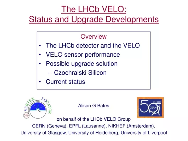
The LHCb VELO: Status and Upgrade Developments. Overview The LHCb detector and the VELO VELO sensor performance Possible upgrade solution Czochralski Silicon Current status. Alison G Bates on behalf of the LHCb VELO Group CERN (Geneva), EPFL (Lausanne), NIKHEF (Amsterdam),

E N D
The LHCb VELO: Status and Upgrade Developments • Overview • The LHCb detector and the VELO • VELO sensor performance • Possible upgrade solution • Czochralski Silicon • Current status Alison G Bates on behalf of the LHCb VELO Group CERN (Geneva), EPFL (Lausanne), NIKHEF (Amsterdam), University of Glasgow, University of Heidelberg, University of Liverpool
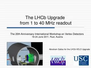
Tracker Silicon VErtex LOcator Magnet ECAL HCAL Muons LHCbAim: to study CP violation in B meson systems • Detector at the LHC analysing 14 TeV proton-proton collisions • ~1012 bb pairs produced every operational year Angular acceptance 15 - 300mrad Trigger tracker Proton interaction region RICH 1 Forward spectrometer RICH 2 IEEE NSS - Rome
Downstream Interaction region ~1m VErtex LOcator - Vertex reconstruction is a fundamental requirement for LHCb • 21 silicon tracking stations placed along the beam direction • 2 retractable detector halves for beam injection periods (up to 30 mm) 21 stations Retractable detector halves IEEE NSS - Rome
R-measuring sensor: (concentric strips) F–measuring sensor: (Radial strips with a stereo angle) VELO Sensor design • 2 sensor types: R and F • R measuring gives radial position • F measuring gives an approximate azimuthal angle • Varying strip pitch • 40 to 102 mm (R – sensor) • 36 to 97 mm (F – sensor) • First active silicon strip is 8.2 mm from the beam line • n+-on-n DOFZ silicon • minimises resolution and signal loss after type inversion • Double metal layer for detector readout IEEE NSS - Rome
VELO in the Vacuum Double sided modules (1 x R and 1 x F sensor) 16 Beetle chips Silicon Sensor TPG* substrate with carbon fibre frame Secondary vacuum Chamber Retracting Detector Half Cooling contacts Carbon fibre paddle Silicon operating temperature -7oC IEEE NSS - Rome *Thermalised Pyrolytic Graphite
Illustration of Vdep … Vdep R/cm VELO environment • VELO sensors operate in a harsh non-uniform radiation environment • fluence to inner regions 1.3 x 10¹⁴neq./cm2 • fluence to outer regions 5 x 10¹²neq./cm2 • Estimated to survive 3 years IEEE NSS - Rome
May 2004 test beam results 300mm n+-on-n R sensor 300mm S:N =18:1 200mm S:N =12:1 16 readout chips (Beetle 1.3) Prototype hybrid (K03) spillover: signal at 25ns after peak in % of the peak signal 30% (100V bias) (30% is the maximum before displaced vertex trigger performance degraded.) IEEE NSS - Rome
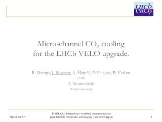
Possible upgrade choices for 2010n+-on-p, pixels, 3D, …many possibilities • Magnetic Czochralski silicon • Standard industrial method of producing silicon • Cheap • Naturally high Oxygen content • more radiation hard? • Test beam at the CERN SPS of a MCz detector* before and after irradiation • LHC speed electronics (40 MHz) (3 SCTA (analogue) chips) • p+-on-n MCz material • Area read out = 6.1 x 1.92 cm • 380 mm thick, 50 mm pitch *Many thanks to the Helsinki Institute of Physics for the MCz detector IEEE NSS - Rome
MCz test beam results Signal [ADC Counts] Signal [ADC Counts] Bias Voltage [V]] Bias Voltage [V]] • Depleted the detector (~550 V) (CV measured Vdep ~ 420 V) • 1.3 x 10¹⁴ 24 GeV p/cm2 S/N = 15 • 4.3 x 10¹⁴ 24 GeV p/cm2 S/N = 11 (under depleted) • 7.0 x 10¹⁴ 24 GeV p/cm2 S/N = 7 (under depleted) S / N > 23.5 + 2.5 (380 mm thick) IEEE NSS - Rome
Further MCz benefits • The VELO currently uses n+-on-n DOFZ silicon detectors • This is necessary because we want material where the high field side is always on the strip side in order to prevent loss of resolution and signal • However, n+-on-n is expensive and restricts the choice of processing company (requires double-sided processing) We have found that MCz does not type invert using the Transient Current Technique (measured to 5 x 10¹⁴ p/cm2)* *Work performed under the PH-TA1/SD group, CERN (A Bates & M Moll) IEEE NSS - Rome
Transient Current Technique - experiment which probes the electric field inside the detectorstype inversion in FZ silicon F = 1.74x10¹³ 24 GeV/c p F= 3.61x10¹⁴ 24 GeV/c p IEEE NSS - Rome
TCT in MCz MCz silicon always has the high field on the strip side of the detector => standard p+-on-n MCz detectors could replace the VELO n+-on-n DOFZ silicon, however, further investigation of the radiation tolerance of MCz is required High field I [V/50Ohms] Low field IEEE NSS - Rome 14 Time [ns]
Status & Conclusions • The VELO is moving from the last prototype testing to sensor production • first pre-production sensors are just arriving (October 2004) • test beam of final module configuration in November 2004 • R&D for possible upgrade solutions is continuing e.g. for MCz • first operation of full size MCz sensor with LHC speed electronics in test beam • further test beam studies planned • non-inversion of MCz material under radiation demonstrated • additional microscopic studies underway IEEE NSS - Rome
p+ Hole movement Electron collection n+ 660 nm laser light TCT Review • Illuminate front (p+) or rear (n+) side of detector with 660 nm photons • Light penetrates only a few mm depth • Ramo’s theorem dictates signal will be dominated by one type of charge carrier • I(t) = q E(u(t)) u(t)drift • e.g. hole dominated curent (hole injection) • Illuminate rear (n+) side of detector IEEE NSS - Rome Time [ns]
Signal treatment • Deconvolution of the true signal from the measured signal Measured signal = detector signal transfer function Transfer function: I(t)=tTCT/R x dUosc(t)/dt + Uosc(t)/R R = 50W from input of preamp tTCT= RCd (Cd = detector capacitance) IEEE NSS - Rome
Back up slide 2 – signal examples Black = signal as measured on the scope Red = Trapping corrected signal IEEE NSS - Rome
FZ (f2) IV/CV analysis Vfd [V] • CV measurements - 10kHz • Measurement at room temperature, then corrected to 20oC • Guard rings grounded • Annealed for 4 min / 80oC 24 GeV/c Proton Fluence [cm-2] DOFZ (d1) Vfd [V] MCz (n320) 24 GeV/c Proton Fluence [cm-2] Vfd [V] DOFZ (W317) Vfd [V] IEEE NSS - Rome 24 GeV/c Proton Fluence [cm-2] 24 GeV/c Proton Fluence [cm-2]
TCT Diagram • Custom written LabVIEW DAQ • ROOT analysis of data Almost no detector shaping from electronics Rise time of signal 1.5 ns Pulse duration min 1.5 ns FWHM IEEE NSS - Rome
MCz IEEE NSS - Rome
test module first telescope station FR RFFR Far station RF CERN SPS X7 120GeV m/p Beam Test: Setup IEEE NSS - Rome Back up slide from D Eckstein, Vertex 2004
Modules recently tested • in June 2004: • 300mm thick PR03 • n-on-n R-sensor • fully populated K03 hybrid • Beetle1.3 tested • many regions read out • in Summer 2003: • 200mm thick PR03 • n-on-n R-sensor • 1 Beetle1.2 on PCB • 1 chip region read out track data not yet analysed – use stand-alone 15 consecutive samples read out Data with tracks in telescope single sample IEEE NSS - Rome Back up slide from D Eckstein, Vertex 2004
Minimum at LHCb startup Minimum requirement for Trigger Maximum requirement from Trigger Beam Test 2003 – Results S/N and Spillover for a set of Beetle Bias settings 300mm extrapolation 200mm measurement spillover: signal at 25ns after peak in % of the peak signal S/N for 200mm at the lower side test 300mm IEEE NSS - Rome Back up slide from D Eckstein, Vertex 2004
300mm measurement 300mm extrapolation 200mm measurement new 2004 Data- Results S/N for 300mm agrees with scaled 200mm • the K03 hybrid (and other components in the chain) do not add noise • S/N in agreement with requirements – should we use the thicker sensors? IEEE NSS - Rome Back up slide from D Eckstein, Vertex 2004
medium strip length shortest strips new 2004 Data- Results it is safer to run at ~100V IEEE NSS - Rome Back up slide from D Eckstein, Vertex 2004