Download
1 / 39
400 likes | 602 Views
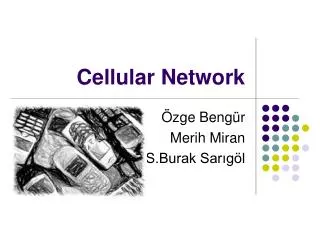
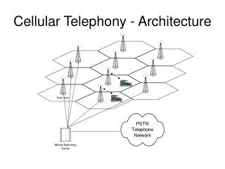
Cellular Mobile Evolution Network Architecture. Supervisor : Dr. Shawky Shaaban Eng. Amir Alaa. Cellular Network. Cell Geometry. Dead Spot. Omni Directional Antennas: Omni directional antennas suffer from dead spots problem. R. R. Cell Geometrical Antennas. R.

E N D
Cellular Mobile EvolutionNetwork Architecture Supervisor: Dr. Shawky Shaaban Eng. Amir Alaa 39
Cell Geometry Dead Spot 39 Omni Directional Antennas: Omni directional antennas suffer from dead spots problem.
R R Cell Geometrical Antennas R 39 • Cell Geometrical Shapes: • Cellular shapes solved dead spots problem • Hexagonal cells: • Minimum number of cells required to cover certain area • Trade offs: • The number of cells required to cover certain area • The cell transceiver power
Transceiver Antenna 39 Sectorial Antenna Omni-Directional Antenna
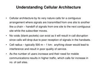
Cell Classification 39 • There are several types of cells: • Macrocells. • Microcells • Picocells • Femtocells • Umbrella cells System design differs based on environment
Cellular Clusters 39 • Frequency Reuse: • Reuse Distance: • Cluster: • A group of cells, where each frequency is exactly used once. • Cluster size (N): • the number N of cells within a cluster is given by: Typical values for N 3, 4, 7, 12
A3 A3 A3 A3 A3 A3 A3 A3 A3 A3 B3 B3 B3 B3 B3 B3 B3 B3 B3 B3 A2 A2 A2 A2 A2 A2 A2 A2 A2 A2 B2 B2 B2 B2 B2 B2 B2 B2 B2 B2 A1 A1 A1 A1 A1 A1 A1 A1 A1 A1 B1 B1 B1 B1 B1 B1 B1 B1 B1 B1 C3 C3 C3 C3 C3 C3 C3 C3 C3 C3 C2 C2 C2 C2 C2 C2 C2 C2 C2 C2 C1 C1 C1 C1 C1 C1 C1 C1 C1 C1 3/9 Cluster • Cluster Specifications: • 3 Cells • 9 Cells • Frequencies are divided into 9 cells distributed by 3 groups 39
A3 A3 A3 A3 A3 A3 A3 A3 A3 A3 A3 A3 B3 B3 B3 B3 B3 B3 B3 B3 B3 B3 B3 B3 A2 A2 A2 A2 A2 A2 A2 A2 A2 A2 A2 A2 B2 B2 B2 B2 B2 B2 B2 B2 B2 B2 B2 B2 A1 A1 A1 A1 A1 A1 A1 A1 A1 A1 A1 A1 B1 B1 B1 B1 B1 B1 B1 B1 B1 B1 B1 B1 C3 C3 C3 C3 C3 C3 C3 C3 C3 C3 C3 C3 D3 D3 D3 D3 D3 D3 D3 D3 D3 D3 D3 D3 C2 C2 C2 C2 C2 C2 C2 C2 C2 C2 C2 C2 D2 D2 D2 D2 D2 D2 D2 D2 D2 D2 D2 D2 C1 C1 C1 C1 C1 C1 C1 C1 C1 C1 C1 C1 D1 D1 D1 D1 D1 D1 D1 D1 D1 D1 D1 D1 4/12 Cluster • Cluster Specifications: • 4 Cells • 12 Cells • Frequencies are divided into 12 cells distributed by 4 groups 39
A3 G3 G3 E3 F3 B3 B3 E3 A3 A3 G3 E3 F3 E3 B3 F3 G3 A3 G3 A3 F3 E3 B3 B3 F3 C3 C3 C3 C3 C3 A2 F2 B2 E2 E2 B2 B2 A2 F2 E2 G2 G2 A2 B2 A2 A2 G2 F2 E2 G2 E2 F2 F2 B2 G2 C2 C2 C2 C2 C2 A1 G1 F1 E1 G1 A1 A1 F1 A1 B1 B1 E1 E1 G1 F1 F1 G1 F1 G1 B1 E1 B1 E1 B1 A1 C1 C1 C1 C1 C1 D3 D3 D3 D3 D3 D2 D2 D2 D2 D2 D1 D1 D1 D1 D1 7/21 Cluster • Cluster Specifications: • 7 Cells • 21 Cells • Frequencies are divided into 21 cells distributed by 7 groups 39
Frequency Reuse Interference 39 Adjacent channel interference Co-channel interference
Adjacent Channel interference 39 • Interference resulting from signals which are adjacent in frequencies to the desired signal (Adjacent frequencies are those shifted by 200 KHZ from carrier frequency) • Due to imperfect receiver filters that allow nearby frequencies to leak into pass band. • Solution: • Careful filtering and keeping frequency separation between channels in a given cell site as large as possible.
Co-channel interference 39 • Cells that uses the same set of frequencies are called co-channel cells. • Interference between these cells is called co-channel interference. • Solution: • Keep distance between co-channel cells >= reuse distance
GSM Network 39
SS SS AUC PLMN PLMN PLMN ISDN ISDN ISDN SMSC H L R GWMSC GMSC PSTN PSTN E I R MSC/VLR MSC/VLR BSS BSS BSC/TRC BSC/TRC Air I/f BTS BTS MS GSM Network Structure 39 AUC: Authentication Center BSC: Base Station Controller BSS: Base Station Subsystem BTS: Base Transceiver Station EIR: Equipment Identity Register GMSC: Gateway MSC HLR: Home Location Register ISDN: Integrated Services Digital Network MS: Mobile Station MSC: Mobile services Switching Center PLMN: Public Land Mobile Network PSTN: Public Switched Telephony Network SMSC: Short Message Service Center SS: Switching Subsystem TRC: Transcoder Resources Controller VLR: Visitor Location Register
Mobile Station (MS) 39 • Mobile Station = + • The Mobile Equipment is said to be a Mobile Station if the Subscriber Identity Module ( SIM Card ) is added to it • The SIM Card contains: • A processor and memory that stores: • The international mobile subscriber Identity (IMSI) • The Authentication and ciphering keys.
SIM CARD 39
International Mobile Subscriber Identity (IMSI) 39 • MCC (Mobile Country Code) • International standardized • MNC (Mobile Network Code) • Unique Identification of mobile networks within a country. • MSIN (Mobile Subscriber Identification Number) • Identification of subscriber in his mobile home network.
Mobile Station ISDN Number (MSISDN) 39 CC: Country Code NDC: Network Destination Code SN: Subscriber Number
International Mobile Equipment Identity (IMEI) 39 TAC: Type Approval Code, The first two digits are the code for the country approval. SN: Serial Number.
New TMSI VLR VLR MSC-A MSC-B Temporary Mobile Subscriber Identity Number (TMSI) 39 • The TMSI can be allocated to the mobile subscriber in order to be used instead of his IMSI during all radio communications. The purpose is to keep subscriber information confidential on the air interface. • The TMSI is relevant on the local MSC/VLR level only and is changed at certain events or time intervals. Each local operator can define its own TMSI structure.
Mobile Station Roaming Number (MSRN) 39 • Used for call routing to the MS as MSISDN identifies a subscriber but not the current location in network • CC: Country code of the visited network • NDC: National destination Code of the visited network • SN: Subscriber number assigned by the current VLR and is unique in the current mobile network
Security Features 39 Authentication: to secure network against unauthorized access. Ciphering: to protect subscriber data sent over the radio path against eavesdropping. Subscriber identity privacy. Equipment Identity Check: to prevent fraudulent usage of mobile handsets.
Authentication Center 39 Database connected to the HLR that stores authentication parameters(Triplet) and ciphering keys for mobile subscribers. Protect the network against illegal entrance. The Ki never transmitted to mobile through air pass, only a random number is sent.
Authentication Center RAND SRES Kc Triplet Home Location Register Kc RAND SRES Triplet Visitor Location Register RAND SRES Kc Triplet Production in The Network 39
SRES Ki RAND IMSI Ki RAND Ki Kc Triplet Production in The MS Authentication Algorithm A3 SRES RAND Number Received Ciphering Algorithm A8 Kc 39
Authentication Procedure Rand SRES AUC Kc Access = SRES AUC SRES MS Barred ≠ SIM Card Kc Rand A3 SRES MS Ki A8 Kc 39
GSM Non-Speech Services 39 • Examples of non-speech services: • Fax Calls • Data Calls • Short Message Service (SMS) • Conclusion GSM is a telecommunication network rather than a telephony network.
Further GSM Enhancements 39 • GPRS • General Packet Radio Services ( Up to 171 Kbit/sec) • EDGE • Enhanced Data Rates for GSM Evolution ( Up to 48 Kbit/sec per channel) • UMTS • Universal Mobile telecommunication System (Up to 2 MB)
GPRS Network 39
Why GPRS? 39 Enhancement of GSM data transfer capabilities Packet switching technology High data rate Focus on IP-interworking
GPRS Applications 39 Remote Office Cars Image Transfer ATM Banking Machines Connectivity Download billboard advertisement Vending Machines PTP (mail, cc validation, browsing, ATC …) PTM (multicast & group)
AUC PLMN HLR SMSC Internet Corporate LAN GWMSC X.25 Network SGSN BSC/TRC + PCU BSC/TRC ISDN TE MT GGSN MSC/VLR BTS PSTN IP Backbone network PLMN Architecture EIR Traffic Signaling 39
GPRS Mobile Station Reference Points Gb S R Um Base Station Subsystem GPRS Core Network TA SIM ME TE MT Mobile Station (MS) 39 TE - Terminal Equipment TA - Terminal Adaptor MS - Mobile Station ME - Mobile Equipment SIM - Subscriber Identity Module
GPRSMobile Classes (Modes) 39 • Class A mode of operation: • It allows a MS to have a circuit switched connection at the same time as it is involved in a package transfer. • Class B mode of operation: • It allows a MS to be attached to both CS and PS but it can not use both services at the same time (Suspend & Resume technique). • Class C mode of operation: • It allows an MS only to be attached to one service at the time. An MS that only supports GPRS and not circuit switched traffic will always work in class C mode of operation.
Serving GPRS Support Node (SGSN) Nokia SGSN 39 • The SGSN forwards incoming and outgoing IP packets addresses to/from a mobile station that is attached within the SGSN service area. • The SGSN provides • Packet routing and transfer to and from SGSN. • Ciphering and authentication. • Mobility management
Gateway GPRS Support Node (GGSN) 39 • The GGSN provides: • The interface towards the external IP packet networks. • From the external IP network’s point of view, the GGSN acts as a router for the IP addresses of all subscribers served by the GPRS network. • Both the GGSN and the SGSN collect charging information on usage of the GPRS network resources. GGSN
The Co-Located SGSN and GGSN 39 • The SGSN and GGSN functionalities may be combined in the same physical node (network element), or they may reside in different physical nodes.