Download
1 / 6
70 likes | 81 Views
The main objective of this study is to review the weight optimization and cost reduction of a connecting rod in a Diesel engine. To get the idea about designing the connecting rod, various stresses to be considered while designing the connecting rod .This has entailed performing a detailed load analysis. The most important factors that are concentrated are stress distribution and deflections. In this project the connecting rod is designed with respect to all the available constraints using advanced cad software CATIA. Later the product file is converted to .stp file format standard exchange of product file and imported to ANSYS workbench to find deformation and analytic valve with respect to the model or product definitions. A. Vijay Kumar | K. Mihir | M. Mrudul | P. Pavan Kumar "Design and Analysis of Connecting Rod of Diesel Engine" Published in International Journal of Trend in Scientific Research and Development (ijtsrd), ISSN: 2456-6470, Volume-3 | Issue-3 , April 2019, URL: https://www.ijtsrd.com/papers/ijtsrd23182.pdf Paper URL: https://www.ijtsrd.com/engineering/mechanical-engineering/23182/design-and-analysis-of-connecting-rod-of-diesel-engine/a-vijay-kumar<br>

E N D
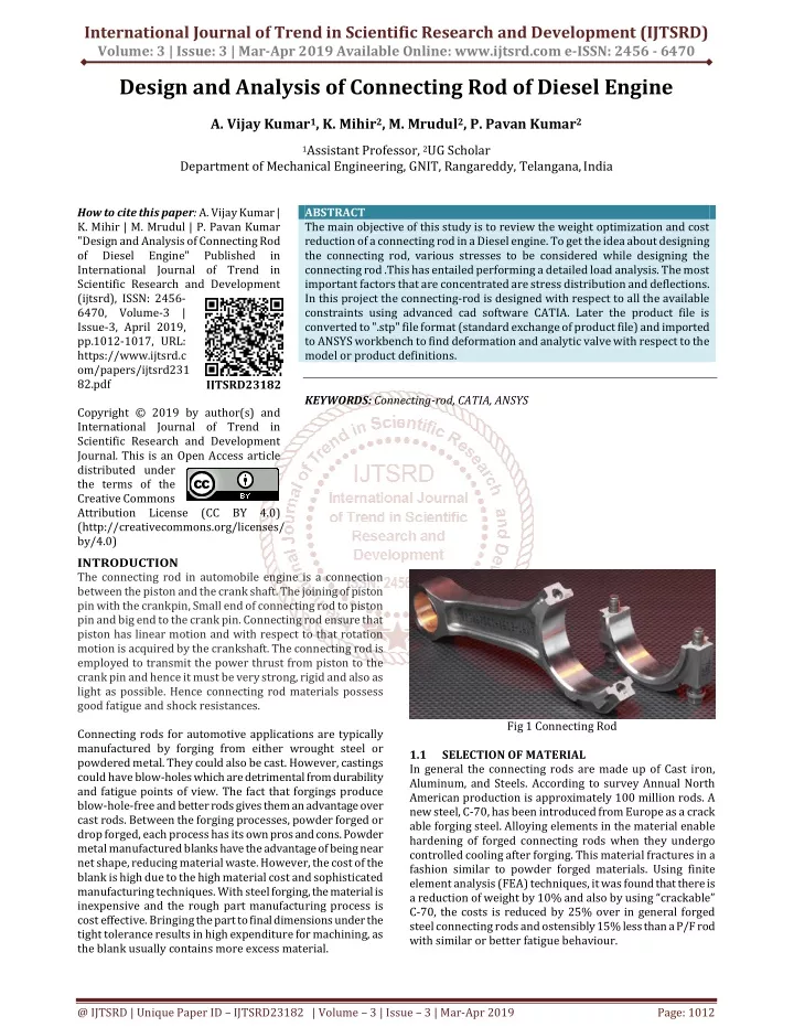
International Journal of Trend in Scientific Research and Development (IJTSRD) Volume: 3 | Issue: 3 | Mar-Apr 2019 Available Online: www.ijtsrd.com e-ISSN: 2456 - 6470 Design and Analysis of Connecting Rod of Diesel Engine A. Vijay Kumar1, K. Mihir2, M. Mrudul2, P. Pavan Kumar2 1Assistant Professor, 2UG Scholar Department of Mechanical Engineering, GNIT, Rangareddy, Telangana,India How to cite this paper: A. Vijay Kumar | K. Mihir | M. Mrudul | P. Pavan Kumar "Design and Analysis of Connecting Rod of Diesel Engine" Published in International Journal of Trend in Scientific Research and Development (ijtsrd), ISSN: 2456- 6470, Volume-3 | Issue-3, April 2019, pp.1012-1017, URL: https://www.ijtsrd.c om/papers/ijtsrd231 82.pdf Copyright © 2019 by author(s) and International Journal of Trend in Scientific Research and Development Journal. This is an Open Access article distributed under the terms of the Creative Commons Attribution License (CC BY 4.0) (http://creativecommons.org/licenses/ by/4.0) INTRODUCTION The connecting rod in automobile engine is a connection between the piston and the crank shaft. The joining of piston pin with the crankpin, Small end of connecting rod to piston pin and big end to the crank pin. Connecting rod ensure that piston has linear motion and with respect to that rotation motion is acquired by the crankshaft. The connecting rod is employed to transmit the power thrust from piston to the crank pin and hence it must be very strong, rigid and also as light as possible. Hence connecting rod materials possess good fatigue and shock resistances. Connecting rods for automotive applications are typically manufactured by forging from either wrought steel or powdered metal. They could also be cast. However, castings could have blow-holes which are detrimental from durability and fatigue points of view. The fact that forgings produce blow-hole-free and better rods gives them an advantage over cast rods. Between the forging processes, powder forged or drop forged, each process has its own pros and cons. Powder metal manufactured blanks have the advantage of being near net shape, reducing material waste. However, the cost of the blank is high due to the high material cost and sophisticated manufacturing techniques. With steel forging, the material is inexpensive and the rough part manufacturing process is cost effective. Bringing the part to final dimensions under the tight tolerance results in high expenditure for machining, as the blank usually contains more excess material. ABSTRACT The main objective of this study is to review the weight optimization and cost reduction of a connecting rod in a Diesel engine. To get the idea about designing the connecting rod, various stresses to be considered while designing the connecting rod .This has entailed performing a detailed load analysis. The most important factors that are concentrated are stress distribution and deflections. In this project the connecting-rod is designed with respect to all the available constraints using advanced cad software CATIA. Later the product file is converted to ".stp" file format (standard exchange of product file) and imported to ANSYS workbench to find deformation and analytic valve with respect to the model or product definitions. KEYWORDS: Connecting-rod, CATIA, ANSYS IJTSRD23182 Fig 1 Connecting Rod 1.1 In general the connecting rods are made up of Cast iron, Aluminum, and Steels. According to survey Annual North American production is approximately 100 million rods. A new steel, C-70, has been introduced from Europe as a crack able forging steel. Alloying elements in the material enable hardening of forged connecting rods when they undergo controlled cooling after forging. This material fractures in a fashion similar to powder forged materials. Using finite element analysis (FEA) techniques, it was found that there is a reduction of weight by 10% and also by using “crackable” C-70, the costs is reduced by 25% over in general forged steel connecting rods and ostensibly 15% less than a P/F rod with similar or better fatigue behaviour. SELECTION OF MATERIAL @ IJTSRD | Unique Paper ID – IJTSRD23182 | Volume – 3 | Issue – 3 | Mar-Apr 2019 Page: 1012
International Journal of Trend in Scientific Research and Development (IJTSRD) @ www.ijtsrd.com eISSN: 2456-6470 LITERATURE SURVEY D. Gopinathan, Ch V Sushma [2015] did research to explore weight reduction opportunities for the production of Forged steel, Aluminum and Titanium connecting rods. First they did static load analysis of connecting rod for three materials and then they optimised forged steel connecting rod for weight reduction. First geometrical model was developed using CATIA. Then product model was analysed by using ANSYS software. Then analysis was compared for three materials for optimisation result. 70 steel, which is break crack able. It kills sawing and machining of the rod and top mating faces and is accepted to lessen the production cos t by 25%. The weight distinction between the two when adjusted for jolt head weight was under 1%. This means that the precision of the strong model. Setup of the motor to which the con-rod has a place. Webster et al. (2000) performed three dimensional finite element analysis of a high diesel engine connecting rod. For this analysis they used the maximum compressive load which was measured experimentally, and the maximum tensile load which is essentially the inertia load of the piston assembly mass. The load distributions on the piston pin end and crank end were determined experimentally. They modeled the connecting rod cap separately, and also modeled the bolt pretension using beam elements and multi point cons equations. Pravardhan S. Shenoy and Ali Fatemi (2005) did the dynamic load examination and enhancement of connecting rod. The fundamental goal of this examination was to investigate weight and cost decrease open doors for a production manufactured steel connecting rod. Normally, an ideal arrangement is the Mini or Max conceivable esteem the target capacity could accomplish under a characterized set of imperatives. The heaviness of the con-rod has little impact on the cost of the last part. Change in the material, bringing about a huge diminishment in machining cost, was the key factor in cost lessening. Thus, in this streamlining issue the cost and the weight were managed independently. The auxiliary elements considered for weight diminishment amid the improvement incorporate the clasping load factor, worries under the heaps, twisting firmness, and hub solidness. Cost diminishment is accomplished by utilizing C- G. M. Sayeed Ahmed [Oct.2014] replaced a broken connecting rod made of forged steel with aluminum alloys and carbon fiber. Connecting rods were manufactured by conventional method. Rods were tested in ideal conditions by applying variable loads. Authors found that weight of connecting rods was reduced and all performed to the level of expectation. Rods performed well at their extreme conditions. DIMENSIONAL PARAMETERS Table 1 Design Specifications Volume of cylinder Height of the bore Bore Radius Gas or Stream Pressure Small end Diameter of connecting rod pin Crank shaft pin diameter of connecting rod Diameter of big end Outer diameter of small end Height of big end Tensile yield stress Load Maximum inertia force on bolts Based on the ranges indulged in design data book the minimum and maximum parameters are considered as case1 and case2. 450cc 95mm 38.8mm 35bar 29.70mm 39.14mm 53.14mm 43.71mm 73.62mm 650 (min) – 950 (max) 15kgf (min), 27.19kgf (max) 6509.393N METHODOLGY 4.1 Modelling of connecting rod in CATIA V5 CATIA is started as an in-house development in 1977 by French aircraft manufacturer AVIONS MARCEL DASSAULT, at that time customer of the CADAM software to develop Dassault's Mirage fighter jet. It was later adopted by the aerospace, automotive, shipbuilding, and other industries. CATIA name dimensional Interactive Application. The French Dassault Systems is the parent company and IBM participate in the software’s and marketing, and catia is invades broad industrial sectors. is an abbreviation for Computer Aided Three- Based on the design particulars above perished the modelling is carried out. The big end and small end are modelled. Both the ends are of connecting rod are assembled by using temporary joints i.e, nut and bolts. Fig Modelling of parts of connecting rod Fig Assembled connecting rod The model is converted into “stp” to undergo the analysis @ IJTSRD | Unique Paper ID - IJTSRD23182 | Volume – 3 | Issue – 3 | Mar-Apr 2019 Page: 1013
International Journal of Trend in Scientific Research and Development (IJTSRD) @ www.ijtsrd.com eISSN: 2456-6470 4.2 Analysis of Connecting Rod by ANSYS 18.1 ANSYS a product of ANSYS Inc. Is a world's leading, widely distributed and popular commercial CAE package. It is widely used by designers/analysis in industries such as aerospace, automotive, manufacturing, nuclear, electronics, biomedical, and much more. ANSYS provides simulation solution that enables designers to simulate design performance directly on the desktop. In this way, it provides fast efficient and cost efficient product development from design concept stage to performance validation stage of product development cycle. It helps to acceleration and streamlines the product development process by helping designers to resolve issues relation to structural thermal fluid flow electromagnetic effect a combination of these phenomena acting together and soon. In ANSYS, the basics of FEA concepts, modelling and the analysing of engineering problem using ANSYS workbench. In addition, describe of importance tools and concepts given whenever required .this following simulation streams of ANSYS. 1. Structural Analysis ?Static Structural Analysis ?Transient Structural Analysis The geometry is imported into the workbench which is stored in “stp” format earlier. The imported model is segregated into set of finite elements by meshig Fig Mesh Generated With Default Mesh Controls The supports and loads are to be specified based on those boundary conditions the analysis is carried out. Also the material specification should be done Fig Choosing the Supports and Loads from Drop-Down 4.2.1 For C-70 Steel Static Structural CASE 1: Fig Total Deformation and Equivalent Stress of connecting rod at first interval Fig Total Deformation and Equivalent Stress of connecting rod at second interval @ IJTSRD | Unique Paper ID - IJTSRD23182 | Volume – 3 | Issue – 3 | Mar-Apr 2019 Page: 1014
International Journal of Trend in Scientific Research and Development (IJTSRD) @ www.ijtsrd.com eISSN: 2456-6470 CASE 2: Fig Total Deformation and Equivalent Stress of connecting rod at first interval Fig Total Deformation and Equivalent Stress of connecting rod at second interval Transient structural CASE 1: Fig Total Deformation and Equivalent Stress of connecting rod CASE 2: Fig Total Deformation and Equivalent Stress of connecting rod Here, The Case 1 is nothing but the modal which is done by using minimal design parameters and load of 15kgf. The Case 2 is nothing but the model which is done by using maximal design parameters and with the load of 27.19kgf. @ IJTSRD | Unique Paper ID - IJTSRD23182 | Volume – 3 | Issue – 3 | Mar-Apr 2019 Page: 1015
International Journal of Trend in Scientific Research and Development (IJTSRD) @ www.ijtsrd.com eISSN: 2456-6470 RESULTS AND DISCUSSIONS 5.1 C-70 Steel: Table 1 Results of C-70 Steel Static Structural Transient Structural First Interval Total Deformation (mm) Second Interval Total Deformation (mm) Total Equivalent Stress (Mpa) Equivalent Stress (Mpa) Equivalent Stress (Mpa) Deformation (mm) Case 1 (Minimum) Case 1 (Maximum) Case 2 (Minimum) Case 2 (Maximum) 0.00020167 0.00022261 0.017118 0.359 289.39 0.39617 319.35 1.5597 0.00016014 0.00029027 0.19648 0.28156 177.06 0.51037 320.96 5.9941 5.2 Cast Iron: Table 2 Results of Cast Iron Static Structural Transient Structural First Interval Total Deformation (mm) Second Interval Total Deformation (mm) Total Equivalent Stress (Mpa) Equivalent Stress (Mpa) Equivalent Stress (Mpa) Deformation (mm) Case 1 (Minimum) Case 1 (Maximum) Case 2 (Minimum) Case 2 (Maximum) 0.00021791 0.00024051 0.017118 0.65066 289.6 0.71803 319.59 1.5597 0.00016059 0.00029111 0.19648 0.51028 177.19 0.92499 321.2 5.9941 5.3 Aluminum: Table 1 Results of Aluminum Static Structural Transient Structural First Interval Total Deformation (mm) Second Interval Total Deformation (mm) Total Equivalent Stress (Mpa) Equivalent Stress (Mpa) Equivalent Stress (Mpa) Deformation (mm) Case 1 (Minimum) Case 1 (Maximum) Case 2 (Minimum) Case 2 (Maximum) 0.00012773 0.00014094 0.017118 1.0033 287.3 1.1072 317.05 1.5597 0.00014416 0.00026134 0.19648 0.78685 175.74 1.4263 318.56 5.9941 5.4 Comparison of Total Deformation for different materials Chart 1 Comparison in between different materials @ IJTSRD | Unique Paper ID - IJTSRD23182 | Volume – 3 | Issue – 3 | Mar-Apr 2019 Page: 1016
International Journal of Trend in Scientific Research and Development (IJTSRD) @ www.ijtsrd.com eISSN: 2456-6470 Here, The Case 1 is nothing but the modal which is done by using minimal design parameters and load of 15kgf. The Case 2 is nothing but the model which is done by using maximal design parameters and with the load of 27.19kgf. By observing the above chart it is clear that the component made up C-70 steel has lesser deformation than Aluminium and Cast Iron. Therefore it is more feasible to use the C-70 steel for the manufacturing of connecting rod. Being a composite material C-70 steel has weight deduction by around 10% of the original components, also the cost reduced according to that. CONCLUSION In this project the connecting rods are Designed concerning all the accessible limitations utilizing a data book as the reference, Later the item’s document are changed over to ".STP" record organize (standard trade of item document) and imported to Ansys workbench to discover disfigurement and investigative valve regarding the model’s definitions. In this project the connecting rod was experienced with different sorts of materials like cast iron, aluminum, and C- 70 to discover total deformation, and equivalent stress by Using static auxiliary features which are included in Ansys workbench. It was observed that connecting Rod made up of Aluminum, and Cast Iron has higher intensity of stress induced as compared to connecting Rod made up of C-70. Also there is a great opportunity to improve the design. Hence C-70 is better choice for connecting rods. REFERENCES [1]D. Gopinathan, Ch V Sushma, (2015) “Design And Optimisation Of Four Wheeler Connecting Rod Using Finite Element Analysis” Materials Today Proceedings 2(2015)2291-2299 [2]G. M. Sayeed Ahmed,(oct. 2014)” Design, Fabrication And Analysis Of a Connecting Rod with Aluminum Alloys and Carbon Fiber” International Journal of Innovative Research in Science, Engineering and technology(IJIRSET),Vol.3,Issue 10, ISSN:2319-8753 [3]Pravardhan S. Shenoy , (2005), “Connecting Rod Optimization for Weight and Cost Reduction”, The University of Toledo, SAE intemational. 2005-01-0987. [4]Abhinav Gautam, K Priya Ajit, (Nov – Dec 2013) “Static Stress Analysis of Connecting Rod Using Finite Element Approach”, IOSR Journal of Mechanical and Civil Engineering (IOSR-JMCE), Volume 10, Issue 1 ISSN: 2278-1684 @ IJTSRD | Unique Paper ID - IJTSRD23182 | Volume – 3 | Issue – 3 | Mar-Apr 2019 Page: 1017