Download
1 / 6
60 likes | 63 Views
In this work, a detailed study has been done to investigate flow of air over the vehicle and various methods have been discussed to check the effectiveness in particular cases, methods like vortex generators, guided vanes, tail plates, rear spoilers, angled diffusers, rear under body slicing ,splitter plates and exhaust gas redirection have been reviewed. The main aim of the review study was to know the factors affecting Coefficient of drag and lift. Of all mentioned techniques and methods, vortex generator and tail plates were found more effective in reducing the drag coefficient as well as the lift coefficient. The study proposed that CFD methods application is proving to be an effective method of improving aerodynamics of a vehicle. Er. Ajay Rana "Methods of Improving Aerodynamics of a Vehicle- A Review" Published in International Journal of Trend in Scientific Research and Development (ijtsrd), ISSN: 2456-6470, Volume-2 | Issue-4 , June 2018, URL: https://www.ijtsrd.com/papers/ijtsrd14588.pdf Paper URL: http://www.ijtsrd.com/engineering/mechanical-engineering/14588/methods-of-improving-aerodynamics-of-a-vehicle--a-review/er-ajay-rana<br>

E N D
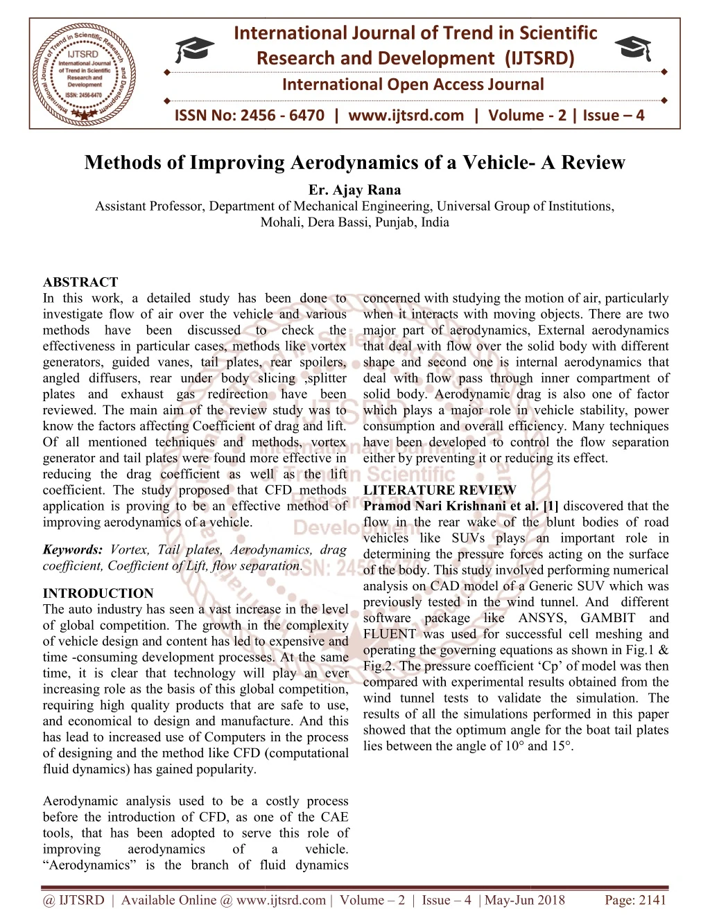
International Research Research and Development (IJTSRD) International Open Access Journal mproving Aerodynamics of a Vehicle- International Journal of Trend in Scientific Scientific (IJTSRD) International Open Access Journal ISSN No: 2456 ISSN No: 2456 - 6470 | www.ijtsrd.com | Volume 6470 | www.ijtsrd.com | Volume - 2 | Issue – 4 Methods of Improving - A Review Er. Ajay Rana Assistant Professor, Department Department of Mechanical Engineering, Universal Group of Institutions Universal Group of Institutions, Mohali, Dera Bassi, Punjab Mohali, Dera Bassi, Punjab, India concerned with studying the motion of air, particularly when it interacts with moving objects. There are two major part of aerodynamics, External aerodynamics that deal with flow over the solid body with different shape and second one is internal aerodynamics that deal with flow pass through inner compartment of solid body. Aerodynamic drag is also one of factor which plays a major role in vehicle stability, power consumption and overall efficiency. Many techniques have been developed to control the flow separation either by preventing it or reducing its effect. LITERATURE REVIEW Pramod Nari Krishnani et al. [1] flow in the rear wake of the blunt bodies of road vehicles like SUVs plays an import determining the pressure forces acting on the surface of the body. This study involved performing numerical analysis on CAD model of a Generic SUV which was previously tested in the wind tunnel. And different software package like ANSYS, GAMBI FLUENT was used for successful cell meshing and operating the governing equations as shown in Fig.1 & Fig.2. The pressure coefficient ‘Cp’ of model was then compared with experimental results obtained from the wind tunnel tests to validate the simul results of all the simulations performed in this paper showed that the optimum angle for the boat tail plates lies between the angle of 10° and 15°. lies between the angle of 10° and 15°. ABSTRACT In this work, a detailed study has been done to investigate flow of air over the vehicle and methods have been discussed to check the effectiveness in particular cases, methods like vortex generators, guided vanes, tail plates, rear spoilers, angled diffusers, rear under body slicing ,splitter plates and exhaust gas redirection have been reviewed. The main aim of the review study was to know the factors affecting Coefficient of drag and lift. Of all mentioned techniques and methods, vortex generator and tail plates were found more effective in reducing the drag coefficient as well as the li coefficient. The study proposed that CFD methods application is proving to be an effective method of improving aerodynamics of a vehicle. In this work, a detailed study has been done to investigate flow of air over the vehicle and various methods have been discussed to check the effectiveness in particular cases, methods like vortex generators, guided vanes, tail plates, rear spoilers, angled diffusers, rear under body slicing ,splitter plates and exhaust gas redirection have been eviewed. The main aim of the review study was to know the factors affecting Coefficient of drag and lift. Of all mentioned techniques and methods, vortex generator and tail plates were found more effective in reducing the drag coefficient as well as the lift coefficient. The study proposed that CFD methods application is proving to be an effective method of concerned with studying the motion of air, particularly when it interacts with moving objects. There are two major part of aerodynamics, External aerodynamics that deal with flow over the solid body with different shape and second one is internal aerodynamics that deal with flow pass through inner compartment of solid body. Aerodynamic drag is also one of factor which plays a major role in vehicle stability, power consumption and overall efficiency. Many techniques have been developed to control the flow separation either by preventing it or reducing its effect. Pramod Nari Krishnani et al. [1] discovered that the flow in the rear wake of the blunt bodies of road vehicles like SUVs plays an important role in determining the pressure forces acting on the surface of the body. This study involved performing numerical analysis on CAD model of a Generic SUV which was previously tested in the wind tunnel. And different software package like ANSYS, GAMBIT and FLUENT was used for successful cell meshing and operating the governing equations as shown in Fig.1 & Fig.2. The pressure coefficient ‘Cp’ of model was then compared with experimental results obtained from the wind tunnel tests to validate the simulation. The results of all the simulations performed in this paper showed that the optimum angle for the boat tail plates Keywords:Vortex, Tail plates, Aerodynamics, drag coefficient, Coefficient of Lift, flow separation coefficient, Coefficient of Lift, flow separation. Vortex, Tail plates, Aerodynamics, drag INTRODUCTION The auto industry has seen a vast increase in the level of global competition. The growth in the complexity of vehicle design and content has led to expensive and time -consuming development processes. At the same time, it is clear that technology will pl increasing role as the basis of this global competition, requiring high quality products that are safe to use, and economical to design and manufacture. And this has lead to increased use of Computers in the process of designing and the method like CFD (computational fluid dynamics) has gained popularity. Aerodynamic analysis used to be a costly process before the introduction of CFD, as one of the CAE tools, that has been adopted to serve this role of improving aerodynamics “Aerodynamics” is the branch of fluid dynamics ynamics” is the branch of fluid dynamics The auto industry has seen a vast increase in the level of global competition. The growth in the complexity of vehicle design and content has led to expensive and consuming development processes. At the same time, it is clear that technology will play an ever increasing role as the basis of this global competition, requiring high quality products that are safe to use, and economical to design and manufacture. And this has lead to increased use of Computers in the process ike CFD (computational Aerodynamic analysis used to be a costly process before the introduction of CFD, as one of the CAE tools, that has been adopted to serve this role of improving aerodynamics of of a a vehicle. vehicle. @ IJTSRD | Available Online @ www.ijtsrd.com @ IJTSRD | Available Online @ www.ijtsrd.com | Volume – 2 | Issue – 4 | May-Jun 2018 Jun 2018 Page: 2141
International Journal of Trend in Scientific Research and Development (IJTSRD) ISSN: 2456-6470 Fig.3. Assembly 3D CAD model of vehicle with different spoiler Patrick Gillie´ron et al.[3] worked on the capacity of vertical splitter plates placed at the front or the rear of a simplified car geometry to reduce drag as shown in Fig.4,5 and 6, with and without skew angle for Reynolds numbers between 1.0 9 106 and 1.6 9 106. The geometry used was a simplified geometry to represent estate type vehicles, for the rear section, and MPV-type vehicle. Drag reductions of nearly 28% were obtained for a zero skew angle with splitter plates placed at the front of models of MPV or utility vehicles. The results demonstrated the advantage of adapting the position and orientation of the splitter plates in the presence of a lateral wind. With vertical splitter plates positioned downstream of a straight base, drag reductions of nearly 12% were obtained and a drag reductions of nearly 27%and 45% were obtained, respectively, using splitter plates positioned upstream of an angled front face with or without an inclination from vertical. Fig.1. Meshing near the Boat tail plates Fig.2. Magnitude velocity path lines for Simulation V. N. Kumar et al [2] worked on a sedan car with different types of spoilers for finding out drag and lift forces at different velocities. The design of sedan car was made on CATIA-2010 and analysis was performed in ANSYS-fluent solver. In this analysis two styles of spoilers were applied, primary spoiler was a “wing” type spoiler mounted 28cm above the surface of car’s rear end , and the 2d spoiler was hooked up edge of the rear aspect of the car without leaving space between the spoiler and the surface of the car as shown in Fig.3. Comparison of drag and lift forces without spoiler, with spoiler 1 and with spoiler 2 at different velocities were obtained .using wing shape spoiler drag coefficient is reduced from 0.333 to o.329. The external aerodynamics simulation is one of the most challenging and crutical automotive CFD application. It integrates fluid mechanics disciplines, mathematics and computer science. The main aim of work is to reduce the lift coefficient to enhance stability on the road. Spoilers are one of the most common devices for introducing downward force on a moving vehicle. Fig.4. Upstream splitter plate type geometry Fig.5. Downstream splitter plate type geometry @ IJTSRD | Available Online @ www.ijtsrd.com | Volume – 2 | Issue – 4 | May-Jun 2018 Page: 2142
International Journal of Trend in Scientific Research and Development (IJTSRD) ISSN: 2456-6470 averaged pressures and individual pressure taps were located to measure the pressures depending on the regions where the sensitivity of pressure loading is important towards the drag. Measurements were carried out with relatively low turbulence in the on- coming wind. Two types of vortex generators were investigated. The locations of the vortex generators were also varied. Following test cases have been carried out for all three wind speeds: 1.Experiment on model without VG (notation as, ‘without VG’). 2.Model with delta shaped VG located after front windshield (with VG1). 3.Model with right angled VG located after front windshield (with VG2). 4.Model with delta shaped VG located after roof end (VG1 back). 5.Model with both VG one i.e. VG1 back and with VG2 (notation as, ‘both VG’). One of the configurations of the vortex generators, when located near the front end of the roof of the car, led to significant reduction in drag coefficient, for the case of wind acting parallel to the length of the car. A percentage reduction in the drag of about 22% was observed for the selected configurations of the vortex generators and for the positions under study. Fig.6. Velocity distribution and streamlines R. B. Sharma et al. [4] performed experiment using tail plate to reduce drag. In this study model of passenger car has been developed in solid works-10 and analysis work was conducted on ANSYS workbench 14.0 fluent platform then after testing and simulation has been performed for the evaluation of drag coefficient for car. In another case, the aerodynamics of the most suitable design of tail plate is introduced and analyzed for the evaluation of drag coefficient for car. The new model of car was designed in Solid Works. Fig. 7 show the car model used in the present CFD simulation. The maximum value of the coefficient of drag is 0.3512 and the Maximum value of the coefficient of lift is 0.2310 for the base model. The Tail plates are placed at back side of the roof and at the tail bumper of the passenger car at 12 degree inclination angle. With Tail plates, the maximum value of the Coefficient of drag (CD) is 0.3376 and the Maximum value of the coefficient of lift (CL) is 0.1926. Thus, it is concluded that, the drag coefficient is reduced 3.87% and lift coefficient is reduced 16.62% with installation of tail plates. Fig.8. Different sections in a car model with locations of VG and pressure taps Gopal P et al.[6] carried out experimental investigation on coefficient of lift and drag with and without vortex generator on the roof of a utility automobile at various yaw angles (10°, 15°and 20°).A scale down model 1:15 of utility vehicle with velocities of 2.42, 3.7, 5.42 and 7.14m/s are tested in wind tunnel as shown in Fig.9. An exceptional reduction in drag force can be obtained by the application of VG. Experimental results showed that Fig.7. Solid work model of Base Car and Passenger car with tail plates S. Selvi Rajanet al. [5] in this study a 1:10 scale model of a car was fabricated in wood and instrumented through a total of 180 pressure taps over the entire top region of the car as shown in Fig.8. Area @ IJTSRD | Available Online @ www.ijtsrd.com | Volume – 2 | Issue – 4 | May-Jun 2018 Page: 2143
International Journal of Trend in Scientific Research and Development (IJTSRD) ISSN: 2456-6470 drag coefficient reduced maximum for Vortex Generator with 15° yaw angle at lower velocity and the lift coefficient remains constant for VG with varying yaw angle at higher velocities and different drag reduction techniques such as rear under body modification and exhaust gas redirection towards the rear separation zones. Through a numerical process (Finite Volume Method) of solving the Favre-averaged Navier-Stokes equations backed by k–epsilon turbulence model, the drag coefficient of the car under analysis is found to be 0.3233 and it is evident that the drag can be reduced up to 22.13% by different rear under-body modifications and up to 9.5% by exhaust gas redirection towards the separated region at the rear of the car. It is also evident that if somehow the negative pressure area and its intensity at the rear of the car can be minimized, the separation pressure drag is subsequently reduced. Fig.9. Scale Model and location of tapping points Akshay Parabet al. [7] in this work a model of a car was created in Solidworks 2013 and was analyzed using software Fluent- Ansys 14.5. In this work laminar flow was solved using Navier-Strokes equations and and turbulent flow was solved using Reynolds Averaged Navier-Strokes method. The main parameters studied were lift and drag coefficients and to calculate the accurate value in drag and lift the vehicle was modified in geometry for this purpose a diffuser at 8 degree, 10 degree and 15 degree was tried out of which the diffuser at 8 degree showed a definite improvement in the vehicle lift characteristics with negligible drag penalty. Such modifications could be carried out in the selected car to improve its handling capabilities at higher speeds thereby improving the overall safety of the vehicle. Fig.11. Different sections in a car model with locations of VG and pressure taps K. Selvakumar et al [9] tested the effect of bump – shaped vortex generator attaching on the roof end of a sedan car using both computational tools and wind tunnel experiment as shown in Fig.12. Both experimental and computational method show that drag force increases with velocity for both base and VG model. After the application of VG, a comparative reduction in drag coefficient value is observed .Due to the application of VG, a downforce creates which pushes the car to the ground resulting more stability at high velocity. Fig.10. Turbulence Energy before and after addition of diffuser S.M. Rakibul Hassanet al. [8] worked on aerodynamic drag reduction using diffuser as shown in Fig. 11. According to this study faster acceleration, is possible by reducing the drag force by optimizing its shape to ensure stream-lining or reducing the separation. This study concentrated on different aspects analysis of aerodynamic drag of racing cars @ IJTSRD | Available Online @ www.ijtsrd.com | Volume – 2 | Issue – 4 | May-Jun 2018 Page: 2144
International Journal of Trend in Scientific Research and Development (IJTSRD) ISSN: 2456-6470 Fig.12. Installation of vortex generators in the base model and the flat roof and bodyside, which affect both drag and lift. Rehan Salahuddin Khan [10] in this work Ahmed body (simplified car body) as ground vehicle is considered which is commonly used as test case as shown in Fig.13. The Ahmed body is made up of a round front part, a movable slant plane placed in the rear of the body to study the separation phenomena at 250, 350 angles, and a rectangular box, which connects the front and rear slant plane. Air is used as a working fluid. The inlet velocity of fluid is 40 m/s. k-ε turbulent model used as a standard model. Two separate cases have been solved for two different front radius of Ahmed body R80, R120 and ground clearance at 20mm, 40mm and results are comparing. The results are present in the form of drag coefficient value and flow field which include velocity contour and velocity vector fields. The validation is carried out by simulation around the Ahmed body with the rear slant angle of 250,350 .The actual wind tunnel experimental data are compared with the results obtained. Fig.14. Tapered windsor body for wind tunnel body Abdul Razzaque Ansari [12] founded that the shape of frontal area of the car is main factor of Drag reduction and essential for reducing the fuel consumption. The design of Tata Indica car has been done on Pro-e 5.0 as shown in Fig.15 and the same is used for analysis in Ansys-(fluent). In this study K-e RNG model has been used to analyses the air flow field, the calculation work was done to compare the experimentally and theoretically value of drag coefficient which is provided with the car by the manufacturer. It was observed that theoretical values of drag coefficient and drag force came out to be 0.598 and 231.85, whereas the experimental values of drag coefficient and drag force came out to be 0.841 and 411, which has a small variation of just 0.243, as the values are close enough. So, results could be validated. Fig.13. Ahmed body mounted in the low-speed wind tunnel Jeff howell et al [11] modified a simple car by tapering of the rear upper body on both roof and sides as shown as Fig.14. The effect of taper angle and taper length on drag and lift characteristics are investigated. At a shorter taper length as initial sharp reduction in drag occurs, but this trend is reversed and a local drag peak is experienced for taper angle greater than 10°. At larger taper angles a significant increase in drag can occur for this taper length. A similar anomaly in the drag trend with taper length was identified for the body with roof taper only at one taper angle of 15° [6]. Pressure measurement showed that strong suction is formed at the intersection of the tapered rear surface Fig.15. Car model designed in Pro-e 5.0 CONCLUSION From the above study it can be concluded that aerodynamics play a very crucial role in increasing fuel efficiency of a vehicle. As the vehicle has to face less pressure due to flowing air, it is able to produce more speed by losing less fuel to air drag and at same @ IJTSRD | Available Online @ www.ijtsrd.com | Volume – 2 | Issue – 4 | May-Jun 2018 Page: 2145
International Journal of Trend in Scientific Research and Development (IJTSRD) ISSN: 2456-6470 time will become more stable by reducing lift coefficient. Various drag and lift methods have been mentioned under literature generators, guided vanes, tail plates, rear spoilers, angled diffusers, rear under body slicing ,splitter plates and exhaust gas redirection. Out of all above mentioned techniques, vortex generator and tail plates is more effective in reducing the drag coefficient as well as the lift coefficient. And can provide better results in future when used at different angles. On comparing theoretical and experimental results the range of agreement between the results were found to be enough close, which proves CFD study to be effective in analyzing real life type situation and can help in reducing the cost factor and at same time increase efficiency of vehicles. REFERENCES 1.Pramod Nari Krishnani and Dr. Dongmei Zhou “cfd analysis of drag reduction for a generic suv” in ASME International Mechanical Engineering Congress and Exposition, IMECE2009 (IOSR-JMCE), Vol. 7, No. 5, pp 28-35 5.S. Selvi Rajan, P. Harikrishna, S. Senthilkumar and K. M. Parammasivam”Aerodynamic Drag Reduction on a Sedan Car by Provision of Vortex Generators through Wind Tunnel Studies” DOI: 10.13140/2.1.1680.0967. topic like vortex 6.Gopal P and Senthilkumar T, “Aerodynamic Drag Reduction in a Passenger Vehicle Using Vortex Generator With Varying Yaw Angles”in Journal of Applied Science and Engineering, Vol-7, 2012 7.Akshay Parab et al “Aerodynamic Analysis of a Car Model using fluent Ansys 14.5”Vol1, issue:4,IJRMEE,pp:7-13, 2014. 8.S. M. Rakibul Hassan, Toukir Islam, Mohammad Ali, Md. Quamrul Islam Numerical Study on Aerodynamic Drag Reduction of Racing Cars, Department of Mechanical Bangladesh University of Engineering and Technology, Dhaka-1000, Bangladesh Engineering, 9.K. Selvakumar et al “Experimental Investigations on Optimization of Aerodynamic Characteristics in a Hatchback Model Car” Using vortex Generators, December 2013. Proceedings of 2.V.N .Kumar, K. L .Narayan, L. N. V. Narasimha Rao and Y Sri Ram, “Investigation of Drag and Lift forces over the Profile of Car with Rearspoiler using CFD”in International Journal of Advances in Scientific Research,2015 10.Rehan Salahuddin Khan et al “CFD Aerodynamic Analysis of Ahmed Body” vol: 18, IJETT, 2014, pp: 301-308. 11.Jeff Howell, Martin Passmore, Simon Tuplin “Aerodynamic drag reduction on a simple car – like shape with rear upper body taper”, SAE International journal, Mech syst. 6(1):2013, doi: 10.4271/2013-01-0462 3.Patrick “Aerodynamic drag reduction by vertical splitter plates” springer in Experimental Fluids, DOI 10.1007/s00348-009-0705-7 2010 Gillie´ron and Azeddine Kourta 4.Sharma, R. B., and Bansal, R. (2013) CFD simulation for flow over passenger car using tail plates for aerodynamic drag reduction, IOSR Journal of Mechanical and Civil Engineering 12.Abdul Razzaque Ansari” CFD analysis of aerodynamic design of TATA INDICA car” Vol:8, issue:3,pp:344-354, March 2017. @ IJTSRD | Available Online @ www.ijtsrd.com | Volume – 2 | Issue – 4 | May-Jun 2018 Page: 2146