Download
1 / 4
60 likes | 95 Views
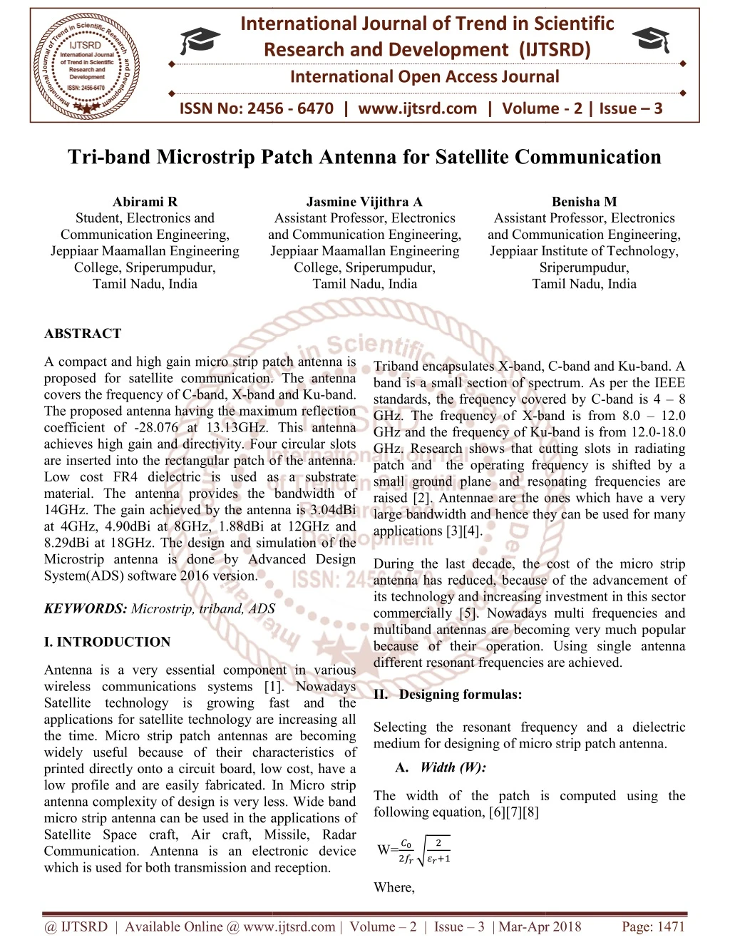
A compact and high gain micro strip patch antenna is proposed for satellite communication. The antenna covers the frequency of C band, X band and Ku band. The proposed antenna having the maximum reflection coefficient of 28.076 at 13.13GHz. This antenna achieves high gain and directivity. Four circular slots are inserted into the rectangular patch of the antenna. Low cost FR4 dielectric is used as a substrate material. The antenna provides the bandwidth of 14GHz. The gain achieved by the antenna is 3.04dBi at 4GHz, 4.90dBi at 8GHz, 1.88dBi at 12GHz and 8.29dBi at 18GHz. The design and simulation of the Microstrip antenna is done by Advanced Design System ADS software 2016 version. Abirami R | Jasmine Vijithra A | Benisha M "Tri-band Microstrip Patch Antenna for Satellite Communication" Published in International Journal of Trend in Scientific Research and Development (ijtsrd), ISSN: 2456-6470, Volume-2 | Issue-3 , April 2018, URL: https://www.ijtsrd.com/papers/ijtsrd11290.pdf Paper URL: http://www.ijtsrd.com/engineering/electronics-and-communication-engineering/11290/tri-band-microstrip-patch-antenna-for-satellite-communication/abirami-r<br>

E N D
International Research Research and Development (IJTSRD) International Open Access Journal band Microstrip Patch Antenna for Satellite Communication Jasmine Vijithra A Assistant Professor, Electronics and Communication Engineering, Jeppiaar Maamallan Engineering College, Sriperumpudur, Tamil Nadu, India International Journal of Trend in Scientific Scientific (IJTSRD) International Open Access Journal ISSN No: 2456 ISSN No: 2456 - 6470 | www.ijtsrd.com | Volume 6470 | www.ijtsrd.com | Volume - 2 | Issue – 3 Tri-band Microstrip Patch Antenna for Satellite Communication band Microstrip Patch Antenna for Satellite Communication Abirami R Benisha M Student, Electronics and Communication Engineering, Jeppiaar Maamallan Engineering College, Sriperumpudur, Tamil Nadu, India Assistant Professor, Electronics and Communication Engineering, Jeppiaar Institute of Technology, Sriperumpudur, Assistant Professor and Communication Engineering, Jeppiaar Institute of Technology Sriperumpudur, Tamil Nadu, India Tamil Nadu, India and Communication Engineering, Jeppiaar Triband encapsulates X-band, C band is a small section of spectrum. As per the IEEE standards, the frequency covered by C GHz. The frequency of X-band is from 8.0 GHz and the frequency of Ku GHz. Research shows that cutting slots in radiating patch and the operating frequency is shifted by a small ground plane and resonating frequen raised [2]. Antennae are the ones which have a very large bandwidth and hence they can be used for many applications [3][4]. During the last decade, the cost of the micro strip antenna has reduced, because of the advancement its technology and increasing investment in this sector commercially [5]. Nowadays multi frequencies and multiband antennas are becoming very much popular because of their operation. Using single antenna different resonant frequencies are achieved. II. Designing formulas: Selecting the resonant frequency and medium for designing of micro strip for designing of micro strip patch antenna. ABSTRACT A compact and high gain micro strip patch antenna is proposed for satellite communication. The antenna covers the frequency of C-band, X-band and Ku The proposed antenna having the maximum reflection coefficient of -28.076 at 13.13GHz. This antenna achieves high gain and directivity. Four circular slots are inserted into the rectangular patch of the antenna. Low cost FR4 dielectric is used as a substrate material. The antenna provides the bandwidth of 14GHz. The gain achieved by the antenna is 3.04dBi at 4GHz, 4.90dBi at 8GHz, 1.88dBi at 12GHz and 8.29dBi at 18GHz. The design and simulation of the Microstrip antenna is done by Advanced Design System(ADS) software 2016 version. KEYWORDS: Microstrip, triband, ADS I. INTRODUCTION A compact and high gain micro strip patch antenna is proposed for satellite communication. The antenna band, C-band and Ku-band. A band is a small section of spectrum. As per the IEEE standards, the frequency covered by C-band is 4 – 8 band and Ku-band. The proposed antenna having the maximum reflection 28.076 at 13.13GHz. This antenna chieves high gain and directivity. Four circular slots are inserted into the rectangular patch of the antenna. Low cost FR4 dielectric is used as a substrate material. The antenna provides the bandwidth of 14GHz. The gain achieved by the antenna is 3.04dBi at 4GHz, 4.90dBi at 8GHz, 1.88dBi at 12GHz and 8.29dBi at 18GHz. The design and simulation of the Microstrip antenna is done by Advanced Design band is from 8.0 – 12.0 GHz and the frequency of Ku-band is from 12.0-18.0 GHz. Research shows that cutting slots in radiating patch and the operating frequency is shifted by a small ground plane and resonating frequencies are raised [2]. Antennae are the ones which have a very large bandwidth and hence they can be used for many During the last decade, the cost of the micro strip antenna has reduced, because of the advancement of its technology and increasing investment in this sector commercially [5]. Nowadays multi frequencies and multiband antennas are becoming very much popular because of their operation. Using single antenna different resonant frequencies are achieved. Microstrip, triband, ADS Antenna is a very essential component in various wireless communications systems [1]. Nowadays Satellite technology is growing fast and the applications for satellite technology are increasing all the time. Micro strip patch antennas are becoming widely useful because of their characteristics of printed directly onto a circuit board, low cost, have a low profile and are easily fabricated. In Micro strip antenna complexity of design is very less. Wide band micro strip antenna can be used in the applications of Satellite Space craft, Air craft, Missile, Radar Communication. Antenna is an electronic device which is used for both transmission and reception. which is used for both transmission and reception. Antenna is a very essential component in various less communications systems [1]. Nowadays Satellite technology is growing fast and the applications for satellite technology are increasing all the time. Micro strip patch antennas are becoming widely useful because of their characteristics of ctly onto a circuit board, low cost, have a low profile and are easily fabricated. In Micro strip antenna complexity of design is very less. Wide band micro strip antenna can be used in the applications of Satellite Space craft, Air craft, Missile, Radar ommunication. Antenna is an electronic device he resonant frequency and a dielectric A. Width (W): The width of the patch is computed following equation, [6][7][8] width of the patch is computed using the W=?? ? ???? ???? Where, @ IJTSRD | Available Online @ www.ijtsrd.com @ IJTSRD | Available Online @ www.ijtsrd.com | Volume – 2 | Issue – 3 | Mar-Apr 2018 Apr 2018 Page: 1471
International Journal of Trend in Scientific Research and Development (IJTSRD) ISSN: 2456-6470 W=Width of the patch ??=Speed of light ??=Value of the dielectric substrate B.Effective refractive index: The radiating wave is travelling from the patch in the direction of ground plane pass through air and some pass through substrate. The amount of the effective dielectric constant ( ?????) is computed using the following equation [6][7][8]: ??? ? ℎ ?????=???? ?+???? ,?ℎ ? >1 ?1 + 12 ?? ? Fig.1 Design of triband antenna C. Length: Calculating the actual rise in length (ΔL) of the patch using the successive equation [6][7][8] (?????+ 0.3)(? (?????− 0.258)(? IV. Result analysis and Calculation: The micro strip patch antenna was simulated and results were analyzed using ADS. ℎ+ 0.264) ℎ+ 0.8) ?? ℎ = 0.412 A.Reflection Coefficient: Where ‘h’=height of the substrate The variation of reflection coefficient in accordance with frequency is illustrated in Fig.2. From Fig.2 the maximum reflection coefficient achieved is -28.076 dB at 13.13 GHz. The bandwidth of the antenna is 14 GHz. The resonant frequency is 13.13 GHz. The length (L) of the patch is instantly be computed using the below equation [6][7][8] ?? L= − 2Δ? ????????? D. Length(Lg) and Width (Wg) of Ground Plane: ??=6h+L ??=6h+W The length and width of a substrate is same as the length and width of the ground plane. III. Antenna Design: Fig.1 shows the design of micro strip patch antenna. FR4 substrate is used as a substrate which is having the relative permittivity ?? of 4.6 and the loss tangent of 0.01. The substrate thickness is 1.6 mm. The proposed antenna resonates at 4 GHz. 50 ohms of input impedance is given through the port of the antenna. The rectangular patch which is having the four circular slots with the radius of 2 mm. The length and width of the patch is 22.4 mm and 17.01 mm as in accordingly and the length and width of the substrate is 32 mm and 26.61 mm respectively. Fig.2 Reflection Coefficient of Proposed antenna B.Gain and Directivity: The simulated gain of proposed antenna with respect to frequency is revealed in Fig.3. Gain is varied from 0.86 dBi to 8.29 dBi at the frequency of 4GHz to 8 GHz. The gain is varied in accordance with frequency. @ IJTSRD | Available Online @ www.ijtsrd.com | Volume – 2 | Issue – 3 | Mar-Apr 2018 Page: 1472
International Journal of Trend in Scientific Research and Development (IJTSRD) ISSN: 2456-6470 Fig.5 Radiation efficiency of antenna Fig.3 Simulated gain Vs frequency plot The radiation efficiency can be derived using the radiated power and the input power accepted by the antenna. Directivity is overall range of of how directional the radiation pattern is. The simulation directivity of antenna in accordance with frequency is depicted from Fig.4. D.Radiation Pattern: Fig.6 displays the radiation pattern of the proposed antenna at 4 GHz and Fig.7 shows the radiation pattern of antenna at 18 GHz. A radiation pattern describes the variation of the power radiated by an antenna as a function of the direction away from the antenna. Fig.4 Simulated directivity Vs frequency plot The directivity and gain of the antenna for different frequencies are presented in Table.1. TABLE.1PARAMETERS OF PROPOSED ANTENNA Frequency (GHz) 4 6 8 10 12 14 16 18 Gain (dBi) 3.04 2.49 4.90 0.86 1.88 2.96 7.79 8.29 Directivity (dBi) 8.63 9.83 10.74 9.64 10.48 9.48 11.20 11.01 Fig.6 Radiation pattern of antenna at 4 GHz C.Radiation efficiency: Fig.5 shows the radiation efficiency of the designed antenna. @ IJTSRD | Available Online @ www.ijtsrd.com | Volume – 2 | Issue – 3 | Mar-Apr 2018 Page: 1473
International Journal of Trend in Scientific Research and Development (IJTSRD) ISSN: 2456-6470 Based on Electric Ring Resonator”, IEEE Antennas and Wireless Propagation Letters 2017, Volume: PP, Issue: 99. 4)Ritika Bansal; Jagriti Bhatia; Amandeep Batth, “A novel lower ultra wideband (UWB) compact planar Inverted-F applications”, 5th International Conference on Reliability, Infocom Optimization (Trends and Future Directions) (ICRITO) 2016, Pages: 464 – 467. Antenna for WBAN Technologies and 5)Prerna “Design and parametric study of rectangular micro -strip patch antenna for Band Satellite Communication”, Conference on Recent Advances and Innovations in Engineering (ICRAIE) 2016, Pages: 1 – 5. Gupta; S. N. Vijay, C- International Fig.7 Radiation pattern of antenna at 18 GHz 6)Ramna, Amandeep Singh Sappal “Design of Rectangular Microstrip Patch Antenna using particle swarm optimization”, Journal of Advanced Research in Computer and Communication EngineeringVol. 2, Issue 7, July 2013. V. Conclusion: A simple design of microstrip patch antenna with slots is proposed in this paper. The designed antenna is radiated from 4 GHz to 18 GHz of triband frequencies. In this paper the antenna achieves high gain upto 8.29 dBi and high directivity. The simulation result shows the antenna reaches high reflection coefficient of -28.076. The performance of the antenna is improved. International 7)J. G. Vera-Dimas, M. Tecpoyotl-Torres, P. Vargas-Chable, J. A. Escobedo-Alatorre and S. Koshevaya “Individual Patch Antenna and Antenna Patch Array for Wi-Fi Communication” Center Engineering and Applied Sciences (CIICAp), Autonomous University (UAEM), 62209, Av. Universidad No.1001, Col Chamilpa, Cuernavaca, Morelos, México. Damián-Morales J. References: 1)Jia Wei, Xing Jiang, Lin Peng, “Ultra Wideband and High Gain Circularly Polarized Antenna with Double-YShape Slot” IEEE Antennas and Wireless Propagation Letters (Volume: PP, Issue: 99) 2017. for Research of of Morelos State 8)Md. MarufAhamed, Kishore Bhowmik, Abdulla Al Suman “Analysis And Design of Rectangular Microstrip Patch Antenna On Different Resonant Frequencies for Communication” International Scientific & Technology Research Volume 1, Issue 5, June 2012. 2)M.H. “Rectangular Ring Micro strip Patch Antennas for Ultra-wide Band Applications”,International journal of innovation and applied studies, vol. 4, pp. 441-446, 2 Oct 2013 Diallo Yaccoub, Achraf Jaoujal, Pervasive Wireless Journal of 3)Irina Vendik, Alexander Rusakov, Komsan Kanjanasit, Jason Hong, Dmitry Filonov, “Ultra- Wideband (UWB) Planar Antenna with Single-, Dual-, and Triple-Band Notched Characteristic @ IJTSRD | Available Online @ www.ijtsrd.com | Volume – 2 | Issue – 3 | Mar-Apr 2018 Page: 1474