Download
1 / 58
590 likes | 781 Views
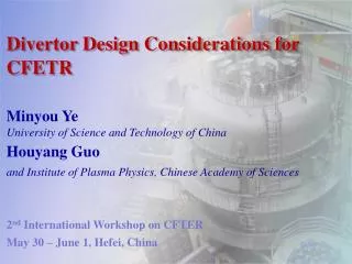
SNST-USTC. Status of design and strategy for CFETR Minyou Ye and CFETR Design Group School of Nuclear Science and Technology, USTC P. R. China Email: yemy@ustc.edu.cn , myye@ipp.ac.cn 26 -28 March 2013 Kyoto Japan. SNST-USTC. Content Introduction background

E N D
SNST-USTC Status of design and strategy for CFETR Minyou Ye and CFETR Design GroupSchool of Nuclear Science and Technology, USTCP. R. China Email: yemy@ustc.edu.cn, myye@ipp.ac.cn26 -28 March 2013 Kyoto Japan
SNST-USTC • Content • Introduction • background • opinion and consideration • Progress on the concept design of CFETR • Summary
Background SNST-USTC • Significant progress of fusion research has been achieved within last 50 years; • International Thermonuclear Experimental Reactor (ITER) has been approved for construction by 7 partners. • In China many important progresses on tokamaks (e.g. EAST, HL-2A) have been achieved during last 20 years; What should be the next step for MFR in China ?
Background SNST-USTC • China is facing serious energy problem (energy shortage and environment pollution). Which will be even more serious in the near future; • Chinese government made the decision to join in ITER. The purpose is to promote the development of the fusion energy for ultimate use as early as possible; • Therefore the National Integration Design group for Magnetic Confinement Fusion Reactor has been founded in 2011 • The design activities of the Chinese Fusion Engineering Test Reactor (CFETR) as the next step are under way by the group.
National design group SNST-USTC Vice heads Head: Wan Yuanxi Li,Jiangang Liu Yong, Wang, Xiaolin Headquarter : SNST-USTC
Working task and schedule SNST-USTC • 2011- 2014: provide twooptions of engineering • concept design of CFETR which should include in: • Missions • Type • Main physics basis • Main techniques basis to be taken • The concept engineering design for all sub-systems • Budget & Schedule • Location • Management system • List of the key R&D items • The plan for 200 PhD students / year • 2015:will make the proposal to government to try to • get permission for CFETR construction;
SNST-USTC • Content • Introduction • background • opinion and consideration • Progress on the concept design of CFETR • Summary
The steps for going to fusion energy ( FPP) • If the fusion energy is goal the necessary steps should be : • achieve the burning plasma : • high density n ; • high temperature T i ; • high energy and particle confinement τE ; • 2. sustain the burning plasma to be SSO or long pulse with high duty cycle : • CW heating : α particles or external heating such as NBI, RF? • CW CD: bootstrap CD ? or external inductive or no-inductive ? • “continual” fueling • CW exhausting the ash of burning by divertor • CW extracting the particle’s energy by divertor • CW extracting the fusion neutron energy by blanket via first wall • Tritium must be self–sustainable by blanket ; • 4.The materials of first wall and blanket have suitable live time ;
Before ITER The most important issue for fusion research is to improve the confinement τE , p --------------------------------------------------------------------------------------- The most important issue for fusion energy is to sustain the burning time tburning
The long burning time for FE is a basic requirement • tburning • --------------------------------------------------------------------------------------------------------------- • Are there good physic and technology basis for SS burning • plasma operation ? Answer is no !! • And how to achieve ? • ---------------------------------------------------------------------------------------------- • How to achieve the T- self-sustain by Blanket ? • What will be happened for key in-vessel components and related • materials under high flux irradiation by 14 MeV neutrons ?
The scientific goals of ITER ITER is the burning plasma device and its scientific goals are: • to produce a plasma dominated by -particle heating• produce a significant fusion power amplificationfactor (Q ≥10) in long-pulse operation (300 - 500s)• aim to achieve steady-state operation of a tokamak (Q=5)• retain the possibility of exploring controlled ignition (Q≥30)• demonstrate integrated operation of technologies for a fusion power plant• test components required for a fusion power plant• test concepts for a tritium breeding module
Gaps between ITER and FPP Even if ITER can make great contribution to long pulse or SSO burning plasma but it is mainly on physics and not on real fusion energy because of the real burning time during 14 year D-T operation is only about 4 %, which results in : • There is no enough fusion energy produced for utilization. • As the consequent the total neutron flux is not enough to demonstrate the real tritiumbreeding for tritium self sustainable by blanket. • No enough neutrons to do the material tests in high flux fusion neutron radioactive environments. • Therefore there only are shielding blankets for ITER. • Even if adding the TBM with addition budget but it is only concept testing for tritium breeding and not real self sustainable blanket and related material tests
Conclusion: the engineering test reactor is necessary to be constructed parallel with or after ITER and before the fusion power plant (FPP). For this purpose the China Fusion Engineering Test Reactor (CFETR) is under discussion seriously for design and construction.
Common understanding (1) • The CFETR must be built before the FPP in China • ITER can be a good basis for CFETR both on SSO burning • plasma physics and some technologies; • The goals of CFETR should be different with ITER and aim to • the problems related with fusion energy • Both physic and technical basis of the CFETR should be more • realistic when it is designed. • CFETR should not make over-promise, it just is a important • engineering test reactor for future DEMO or FPP for FE
Common understanding (1) • So mission must be realistic and sequence must be right !! • The cost for fusion energy , the multi application of blanket • could be lower priority in compare with T selves- sustainable • and heat conversion and extracted; • The divertor will be another key component for the success of • future FPP- it will be the most important components related • with the basic requirements for SSO both on physics and • technologies.
Content • Introduction • some background information • opinion and consideration • Progress on the concept design of CFETR • Summary
The mission and design goal of CFETR • A good complement to ITER; • Relay on the existing ITER physical and technical bases ; • Fusion power Pf = 50~200MW; • Steady-state or long pulse operation (duty cycle ≥ 0.3- 0.5); • Demonstration of full cycle of T self-sustained with TBR ≥ 1.2; • Exploring options for DEMO blanket & divertor with an easily • changeable capability by RH. • CFETR will be the important facility to bridge from ITER to DEMO • in China, which is necessary step to go to DEMO and then the • fusion power plant.
Preliminary design consideration • Physics consideration • Integrated design consideration • of the device with RH • Blanket considerations • Divertor considerations • Tritium consideration
Physics consideration • CFETR as a test reactor to achieve the fusion energy at reasonable fusion power level should have high reliability and availability. So the core plasma designs are based on relatively conservative physics and technology assumptions, such as operation far away from the stability limits and readily achievable performance; • A device of R=5.7m, a=1.65m in size with Bt=5T and total H&CD source power of 80MW (assumed efficiency 0.8) with SN configurationcould be projected based on a zero-dimensional system study using extrapolations of current physics, which are from the multi-iteration and optimization among plasma performance, blanket module and superconducting magnet requirements, etc. • Analysis of vertical stability control indicates that the basis configuration with an elongation kx=2.0 can be reliably controlled using in-vessel coil similar to that used in EAST.
key parameters and several design versions of CFETR are under comparison
Simple scaling for Parameter investigation R(m)=5.7, a(m)=1.65, B(T)=5; κ=2.0, δ=0.4; αn=1, αT=1;Vp(m3)=612; Ip=10MA,q95=4.17, Zeff~1.76,Power deposition80%, gCD = 0.16~0.26 (ITER target 0.4) B.N. Wan et al.,
Conclusion·: • Scenario analysis based on “ITER physics design guidelines” show that CFETR can achieve 200MW fusion power at Ip~10MA in H-mode for over 1000s; • 8.5MA in “improved H-mode" (H98~1.2) for several hours or at Ip~7.5MA for steady-state in advanced regime with a moderate factor of H98~1.3 and beta_N <2.8. Ip~8MA, Bt=5T, q95=5.2, Zeff~1.76, P~80*0.8MW, CD = 0.15~0.22 (ITER target 0.4)
key parameters and several design versions of CFETR are under comparison
Range of key parameters and several design versions of CFETR are under comparison
Preliminary design consideration • Physics consideration • Integration consideration of the • tokamak device with RH • Blanket considerations • Divertor considerations • Tritium consideration
The duty cycle of CFTER will be impacted by the principle of RH significantly
The structure of Case 1 for CFETR The structure of Case 2 for CFETR The structure of Case 3 for CFETR
Preliminary design consideration • Physics consideration • Integration consideration of the • tokamak device with RH • Blanket considerations • Divertor considerations • Tritium consideration
Three groups are working on the concept design of CFETR blanket • Group I: • HC (8MPa, 300/5000C), • Li4SiO4 (Li2TiO3 ), Be , RAFM • Group II : • SLL ( ~150 0 C ) , CLAM • DLL( ~700 0C), CLAM • Group III : • HC, Li4SiO4 , Be , RAFM • WC, Li2TiO3, Be12Ti , RAFM
Group I: HC (8MPa, 300/5000C), Li4SiO4 (Li2TiO3 ), Be , RAFM phase II and III Group II: SLL ( ~150 0 C ) , CLAM DLL( ~700 0C), CLAM Group III: 1) HC, Li4SiO4 , Be , RAFM 2) WC, Li2TiO3, Be12Ti , RAFM
NWL (average): 0.33 MW/m2 • Inboard shielding thickness : ~ 46 cm • Outboard shielding thickness: ~40cm • Inboard breeder thickness: ~ 37cm • outboard breeder thickness: ~ 67cm • TBR can ≧ 1.2 but very sensitive by outboard windows • TBR is impacted by first wall material and thickness; • Difference between 1 D and 3D calculations ~ 15-20% Conclusions
Preliminary design consideration • Physics consideration • Integrated design consideration • of the device with RH • Blanket considerations • Divertor considerations • Tritium consideration
Main Functions of Divertor • Exhaust the major part of the plasma thermal power, reducing heat flux below limitation of target materials (10 MW/m2). • Remove fusion helium ash from core plasma while providing sufficient screeningforimpurities influxes. • Maintain acceptable erosion rate in terms of reactor lifetime.
Considerations of Divertor Design of CFETR • CFETR divertor • configurations: bottom SN • Advantages of SN: • more simple • lager volume of pl. • benefit on TBR
Power handling is the most important issue for the reactor design Injected power (auxiliary heating: 100 MW) Pfus= 200 MW Pheat=100+40 MW Prad=40 MW 100MW Divertor plates
Advanced Divertor Configurations • New options: Super-X, Snowflake • Advantages: • Increase wetted area to reduce peak heat flux • Increase L// to facilitate radiative divertor. • Issues to be addressed: • Minimum number of PF coils • PF current and size • Restrictions of poloidal coil location