Download

1 / 28
350 likes | 812 Views
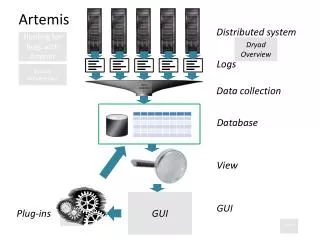
iSOCAN Artemis www.rdstec.com. Part 1 A reminder of the new system. Mk2 MCM. Mk2 MCM. Mk2 HBM. Mk2 HBM. New iSOCAN Artemis Architecture. Job Computer and harness to work with RDS iSOCAN operator interface.

E N D
Mk2 MCM Mk2 MCM Mk2 HBM Mk2 HBM New iSOCAN Artemis Architecture Job Computer and harness to work with RDS iSOCAN operator interface Job Computer and harness to work with 3rd parties ISOBUS compliant Virtual Terminal
Mk2 MCM RDS CAN protocol ISOBUS CAN protocol Mk2 HBM Job Computer contains the Artemis application software to enable functionality with iSOCAN or 3rd party ISOBUS terminal New iSOCAN Artemis Architecture
New iSOCAN Artemis Architecture • Utilises existing hardware as supplied with PSi Artemis so retaining installation familiarity and confidence in reliability of key components i.e. Motor Control Module • Can be retro-fitted in the field for customers wanting an existing drill to function with an ISOBUS compliant VT • Provides a logical stepping stone to the position of only supplying a complete ISOBUS compliant Artemis system
SD slot behind rubber door USB slot behind rubber door RDS iSOCAN Terminal • High Brightness (400mcd) colour, 7” widescreen format (800x480) LCD with touchscreen • 16 backlit physical keys for application specific functions • ARM9 CPU running at 400Mhz • Windows CE6.0 operating system • 2 composite video camera inputs • SD card slot • USB slot • 1.5watt loudspeaker • IP65 sealing • W:227mm x H:157mm x D:45mm
Ethernet (optional) Loudspeaker Camera1 (optional) Camera2 (optional) Emergency Stop Switch (optional) RDS iSOCAN Terminal
Power Up The above will be shown whilst the iSOCAN instrument turns on The above will then be shown whilst the iSOCAN instrument loads all the data from the Job Computer
Main Operating Screen When ready to operate the iSOCAN will default to the MAIN operating screen as shown above
Main Operating Screen Operates Pre-Start Cycles the grey INFO window Cycles through INFO, LOG & MAIN Goes to the optional Auxiliary Function screen Goes directly to the MENU screen Remember, touchscreen or physical buttons can be used! HOME button always returns to this screen Cycles between Artemis and camera inputs (when used)
Camera 1 Use of Camera Input MAIN screen MAIN screen Operator could manually cycle between options using the button shown aboveoran AUTO facility could cycle in a loop based upon operator programmed times i.e. 5 seconds on MAIN, 2 seconds on camera 1, 2 seconds on camera 2, 5 seconds on MAIN etc
3 Products, 3 Motors 2 Products, 4 Motors 1 Product, 1 Motor 2 Products, 2 Motors 1 Product, 2 Motors Configurations Screen shows 4 products,4 motors
Metering Motor switched OFF Metering Motor switched ON Motor turning proportional to forward speed Metering roll animated Metering Motor switched ON Motor stopped due to zero forward speed or cut-out status Metering roll animation stopped Metering Status
Metering Control Press to toggle motor ON/OFF Press to bring up keypad to set target rate. When away from target button becomes ‘Return to Target’
In Work – Symmetrical Tramlining OFF Out of Work – Symmetrical Tramlining OFF In Work – Symmetrical Tramlining ON In Work – Asymmetrical Tramlining Left ON Left OFF – Symmetrical Tramlining OFF Cut-Out Status
Symmetrical Sequence Non – Tramline Bout Symmetrical Sequence Non – Tramline Bout Count Held Symmetrical Sequence Tramline Bout Asymmetric Left Sequence Tramline Bout Tramline Status
Auxiliary Functions Screen Optional Auxiliary Function Screen for operation of electro-hydraulic functions, ½ width actuators etc.
Auxiliary Functions Screen Selects the FOLD or UNFOLD routines Selects the required marker operation Selects the Auxiliary Function Toggles the selected Auxiliary Function ON/OFF Returns to the MAIN screen Returns to the MAIN screen Reminder of useful working information
INFO Screen – Working Totals Shows the working totals Selects the column of totals to be reset Goes to the Grand totals Goes to the Weighing Screen Press to reset the selected column Returns to the MAIN screen 3 registers recording area, working time, product totals and date since last reset.All accumulate simultaneously but can be independently reset as required.
Info Screen – Grand Totals Goes to the working totals Shows the Grand totals Goes to the Weighing Screen Returns to the MAIN screen Non-resettable register of total worked area and time
Info Screen – Optional Weighing Press to start the Loadcell based product calibration routine Shows the ‘live’ hopper weight Shows the area and distance to zero kg’s Information relating to the Loadcell based product calibration routine Returns to the MAIN screen Press to ‘Tare’ the Loadcells when the hopper is empty
Log Screen Press to start the Loadcell based product calibration routine Selects the memory in use Press to start a job Provides a summary of GPS information Press to print the selected job Selects the row of job details to be viewed Returns to the MAIN screen Shows the recorded jobs
MENU Screen This is the screen first encountered in the MENU modes
MENU Screen – ‘Tabs’ Select the required ‘Tab’ or just use the touchscreen Use to select/change the programmable factor Metering Setup Drill Setup Alarm Setup Tramline Setup Instrument Setup Factory Setup Diagnostics
Metering Setup Configuration as per MAIN screen Selects the metering unit Goes to the product calibration routine for the metering unit selected Allows the units and % step size to be changed.TGW and product calibration factor can also be manually set.Speed range is information only based on the motor speed limits