Download
1 / 17
170 likes | 313 Views
Control System Overview . Bob Dalesio Control System Group Leader NSLS-II DOE Status Review June 9-11, 2009. Outline. Design Requirements Technical Requirements & Specifications Cost & Schedule Baseline & Staffing Status Construction Standards Technical Development

E N D
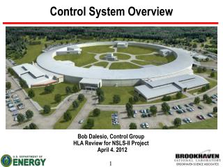
Control System Overview Bob Dalesio Control System Group Leader NSLS-II DOE Status Review June 9-11, 2009
Outline Design Requirements Technical Requirements & Specifications Cost & Schedule Baseline & Staffing Status Construction Standards Technical Development Recent Accomplishments Near Term Plans Conclusions
Control System Requirements – 1 of 3 • Bunch Length 1-40 psecs • 2.642 usec ring revolution • Injection system runs up to 1 Hz • Top off every 1 minute • Top off bunch train ~20 nsec • Top off damping time 10-50 msecs (no extraction) • 80% Fill – 1056 of 1320 buckets filled • different fill patterns • high charge single bunch at mid-gap • Orbit stability to .3 microns at injection • 5 Hz updates to operators of up to 1000 chosen parameters • Archive up to 20,000 parameters once every 5 seconds continually • Must scale to support 150,000 physical I/O connections and 400,000 computed variables • 99.7% availability during operation
Control System Requirements – 2 of 3 • 5 KHz RF Feedback on beam phase • 10 kHz orbit feedback, (100 usec loop time) • 360 BPMs (12 per cell) • 90 Corrector PS (3 per cell) • Slow orbit correction • 180 Slow PS (6 per cell) synchronized with fast orbit feedback • 1 Hz model based control • 10’s of Hz Data Collection for RF loop correction. • 200 MeV to 3 GevV in 400 msec ramp in booster for gap changes • Transverse feed back Bunch to Bunch • 1 H and 1V stripline • RF cavity control • BPM Requirements • Turn by turn on demand • Fast 10 kHz output • Slow 10 Hz data • ADC Raw data • Optical clock below 100 fsec
Control System Requirements – 3 of 3 80 psecs pulse to pulse timing jitter. During top off, some beam lines will need 1.1 - 1.8 psecs of timing jitter Timing resolution 2 nsec for bunch to bunch timing 200 psec for single bunch injection Provide electron detector as event for beam line 10 kHz power supply read backs triggered from timing sys All data available to system with revolution identifier for turn by turn data correlation. 20 msec equipment protection mitigation Transient Recording Take coherent turn by turn orbit data for up to 800channels for 1024 turns Latch the last 10 seconds of data from all parameters in the storage ring Beam line needs 1 msec archiving over 1 minute for temperatures and positions Provide data for all control aspects (no hidden parameters) Conventional facilities Tunnel and experimental floor Vibration < 25nm from 4-50Hz Thermal stability of storage ring tunnel enc +- .1 dgc Experimental floor +- .5 dgc
Budget - $300M ($30M for Controls) • Manpower by FY09 • 4 High Level Application Engineers: Nikolay Malitsky, Guobao Shen, Kunal Shroff, Marty Kraimer (contract), • 2 RDB Architects: Don Dohan, Gabriele Carcassi • 10 Project Engineers: Joe Delong, Kiman Ha, Yong Hu, Jayesh Shah, Michael Davidsaver, Yuke Tian, Daron Chabot, David Dudley, Huijuan Xu, Wayne Lewis • 1 EPICS Expert: Ralph Lange (on sabbatical) • 1 Network Expert: Robert Petkus • 1 position left to fill • Material • IOCs crate, processor, and monitoring (1.3 Million) • $1M network hardware & 360K timing distribution • $400K Servers and Control Room Consoles • $400K Timing System Hardware • $200K test hardware
Control System Software Standards Software standards are being evaluated • EPICS as the control system • IRMIS used for all configuration data: lattice, components, wiring etc. • Embedded Real-Time Operating System choice: RTEMS / Linux • Linux Workstations running Debian • Commissioning physics applications: Matlab Middle Layer Toolkit – MMLT • Model Control: Elegant (APS) and Tracy • Online simulation running under EPICS Process Database (Diamond) • PV Data and PVAccess being used for client/server environment on HLA • Mercurial used source/release control • Experiment Control Tools: SPEC (ubiquitous) and GDA (Diamond) • Operator Tools:CSS w/ BOY, BEAST. Extending for multi-channel arrays • Channel Archiver: watching hyper table developments from INFN.
Control System Hardware Standards Dell Linux development workstations Micro Research Finland – Timing System PLC Solutions – Allen Bradley Non-VME IOCs (240) Moxa VME crates (90) Weiner CPU Boards Motorola MVME 3100, Intel Board?? Motor Controllers Delta Tau Network Switches Brocade Beam Position Monitors, Power Supply Controllers, FOFB hardware is developed in-house. Hardware Components are being selected
Embedded Device Control BPM Controller BPM Controller BPM Controller BPM Controller BPM Controller BPM Controller /OC EPICS RF Clock Distribution 45 MHz PCIx Interface +T0 + - Settling time on BPMs +0.0 usecs - BPM to Compute Controller 384 bits = 64 bits * 6 BPMs 4.9 usecs = 384 bits over 100 MBit enet +4.9 usecs - Compute Controllers to each other 10,290 bits = 30 nodes * 384 bits 10.5 usecs = 10,290 bits over 2 GB enet +15.4 usecs – Compute local matrix 0 usecs + 15.4 usecs - Communicate t Power Supply Controllers 24 = 4 PS * 4 bytes each 3.5 usecs +18.9 usecs – loop complete settling time for magnets communicate diagnostic waveforms etc… +200 usecs – start again Fiducial Distribution 1 Hz Prev Cell Core Controller I/OC EPICS PCIx Interface Core Controller PS Controller PS Controller PS Controller PS Controller I/OC EPICS PCIx Interface 100 MB ENET Next Cell Core Controller 2 GBit ENET
High Level Applications Physics Applications (Thin Client) Physics Applications (Thick Client) Optics Resp.Matrix (S) Lattice Model Server Measured Orbit Orbit Differences Conversions Mid Level Data Client/Server Optics Deviations Name Mapping Gradient Errs & Corrections Application / Family Configuration Parameters Beam R. M. Diff’s Channel Access Data Server EPICS Client/Server Dipole Quad Sext. Corr. BPM RF Design Goal Computed Data Need to port Need to develop IOC Process Database Under development Existing Designed lattice & installed hardware seq
IRMIS Web Based Reports Editor Component Type Component Lattice EPICS Database Name Mapping Wiring Component Type Component Lattice EPICS Database Name Mapping Wiring Components Lattice EPICS Database Name Mapping Wiring Scripts Files for control Component Type Component Lattice EPICS Database Lattice EPICS Database Name Mapping Complete Complete FY 08 Complete FY 09
Random Points • We had some very early help in getting our plan right from Mark Heron and Dave Gurd. They identified key budget areas that were missing. • Identifying areas of development early, makes it possible to make a difference for this project. There is only 3 years from start of the project to start of commissioning • Getting requirements from physicists is one of the more challenging parts of a project. We are most successful by talking to the control groups at other similar projects.
Conclusions • Our capabilities are defined by our group, and we have been very fortunate to attract such great talent. • The developments that we have undertaken are going well in hardware, relational database tools, and high level application architecture. These could be useful in other environments. • The resources available to meet the demands of modern facilities are such that we must expand the areas where we collaborate: hardware, physics applications, experiment control, analysis, etc…