Download
1 / 70
700 likes | 886 Views
DSP 技术与应用. Section 5 程序控制器 Program Sequencer. ADSP-219x Block Diagram. 程序控制器. 确定下一条指令的取指地址 控制 指令流水线 指令缓冲 分支 循环 中断 条件指令的执行. 特点. • 支持: Loops, Jumps, Subroutines, Interrupts, and Idle 指令. • 支持 Hardware Stacks:. - PC Stack: 33-deep, subroutines & interrupt return address

E N D
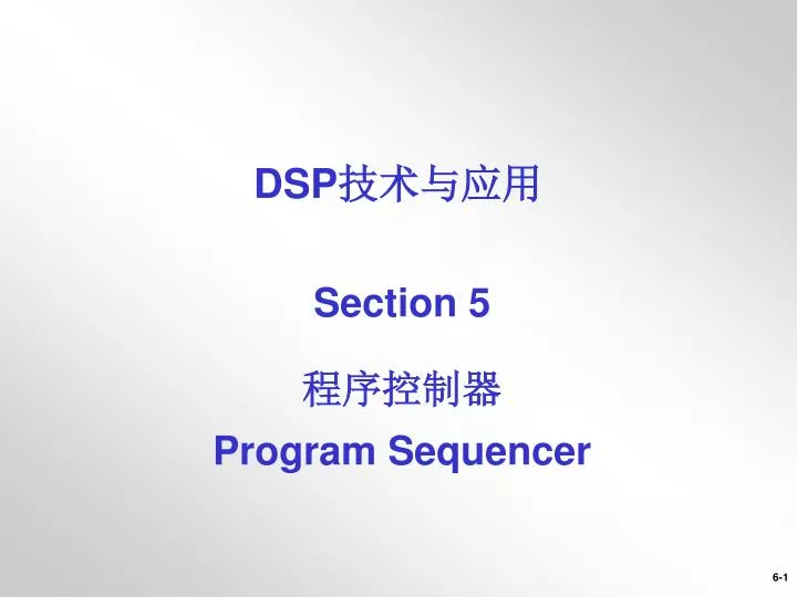
DSP技术与应用 Section 5 程序控制器 Program Sequencer
程序控制器 • 确定下一条指令的取指地址 • 控制 • 指令流水线 • 指令缓冲 • 分支 • 循环 • 中断 • 条件指令的执行
特点 • 支持: Loops, Jumps, Subroutines, Interrupts, and Idle指令 • 支持 Hardware Stacks: - PC Stack: 33-deep, subroutines & interrupt return address - 3 Stacks for Do Loops: Each 8 deep, supports nesting of 8 Do Until Loops - Status Stack: 16-deep, saves ASTAT and MSTAT on interrupts • 6级指令流水线 • Cache allows Three-Bus performance from a two bus system • Allows branching in parallel with computations for increased efficiency • Zero-Overhead Do Until loops up to 8 nested loops • Delayed Jump, Call, RTS, RTI
Program Sequencer LOOP LOGIC LOOP BEGIN STACK ASTAT MSTAT INTERNAL PMD BUS LOOP END STACK STATUS STACK INTERRUPTS (From Core and IOP) COUNTER STACK INSTRUCTION CACHE INTERRUPT LATCH LOOP CONTROLLER INTERRUPT CONTROLLER INTERRUPT MASK INSTRUCTION LATCH INTERRUPT MASK POINTER INTERRUPT LOGIC CONDITION LOGIC SWCOND (CCODE) INSTRUCTION PIPELINE PROGRAM COUNTER DAG1 or DAG2 + Other INSTRUCTION PIPELINE Elements IJPG reg PC STACK 8 DIRECT ADDRESS 16 TOP OF LOOP ADDRESS INTERRUPT VECTOR RETURN ADDRESS 24 +1 INDIRECT BRANCH PC-RELATIVE ADDRESS NEXT ADDRESS MULTIPLEXER PMA BUS
Variations in Program Flow Address: n Instruction DO UNTIL JUMP n+1 Instruction Instruction Instruction n+2 Instruction Instruction Instruction Loop n+3 Instruction Instruction Instruction N Times n+4 Instruction Instruction Instruction n+5 Instruction Instruction Instruction Linear Flow Loop Jump INTERRUPT INTERRUPT CALL Instruction IDLE Instruction Instruction Instruction Instruction Instruction Instruction IRQ vector Instruction Instruction IRQ vector Instruction Instruction Instruction Instruction Instruction Instruction Instruction RTS RTI RTI Subroutine Interrupt Idle
Example Program Sequencer Instructions JUMP somelabel; //PC relative jump CALL somelabel; //PC relative call CALL somelabel (db); //PC relative call using a delayed branch If eq CALL somelabel; // Conditional call RTS; // Return from subroutine RTI; // Return from interrupt service routine IDLE; // wait here for interrupt JUMP i2; // Indirect jump to address pointed to by i2 and IJPG
Conditional Instructions • Most of ADSP-219x instruction can be executed conditionally • No latency for conditional instructions IF EQ AR = AX0 + AY1;IF MV JUMP errorhandler; IF NOT MV MR = MX0 * MY0 (SS);IF AC AR = PASS AX0;
Available Conditions [ IF condition] <instruction>; ALU EQ NE equals zero or not AZLT GE lower than / greather-equal zero AN xor AVLE GT lower equal / greather than zero (AN xor AV) or AZAC NOT AC ALU carry ACAV NOT AV ALU overflowed AV Multiplier MV NOT MV multiplier overflowed MV SpecialsTRUE Always true NOT CE loop counter expired CE[NOT] SWCOND software condition various ALU input sign AS Shifter overflow SV Flag pin input state PF0 .. PF13 register CCODE Example: CCODE = cond_AS; NOP; // one cycle of effect latency IF SWCOND AR = -AX0;
流水线思想 请大家设想一下工厂里产品装配线的情况,在我们想要提高它的运行速度的时候,是怎么做的呢? 把复杂的装配过程分解成一个一个简单的工序,让每个装配工人只专门从事其中的一个细节,这样每个人的办事效率都会得到很大的提高,从而使整个产品装配的速度加快。这就是流水线的核心思想。 过去按照冯·诺依曼型计算机执行程序的原理,指令必须是按顺序方式逐条串行执行的。比如加法指令可以分成取指令、指令译码、取操作数、ALU运算、写结果五个步骤,如果有程序中有连续两条这样的指令,在传统的计算机里必须等第一条指令完全结束才能开始执行,而流水线的好处是:第一条指令开始译码的时候,第二条就可以开始取指令了。
流水线带来的问题 流水线的效率也可能低下,主要有两个原因: 一是如果第一条指令的结果是第二条指令执行所需要的,那么就出现了相关性问题。这就导致流水线必须停下来等前面的运算结束才能够继续后面的指令。现在解决这个问题的办法有乱序执行技术。 另一个原因是程序转移问题,由于我们无法事先判断转移指令会走那一边,所以必须等待结果出现。由于这样的指令在程序中数量众多,通常会导致流水线的停顿状况非常严重。解决的方法一般是通过风险的预测执行或强行并行执行来解决。
超标量技术 如果说流水线是依靠提高每个“操作工人”的效率来达到提高整体效率的目的的话,那超标量就纯粹是在增加“工人”的数量了。它通过重复设置大量的处理单元,并按一定方式连接起来,在统一的控制部件控制下,通过并行操作来完成各自分配的不同任务。如果说流水线等技术是提高CPU部件的重叠使用效率,那么超标量技术则是通过典型的资源重复设置来提高计算机处理速度的方法了。超标量技术从某种程度上讲可以说上阵列处理机的一种典型的应用。 已经应用在了ADI最新的TigerSHARC DSP上。
Instruction Pipeline • 6-Stage Instruction Pipeline • EE-Note 123 explains details • Instructions execute in a single core cycle • No arithmetic pipe-line • Minimal impact upon programming model • Functionally transparent to user • Not required to install software stalls • If necessary, hardware stalls automatically Simulator: check Setting->Preferences->General->Enable pipeline display
Pipeline Stages • Incorporates two-stage memory pipeline
Linear Program Flow Address Instruction[000200] i1 ax1=0; [000201] i2 ay1=0;E[000202] i3 ax0=dm(i0+=m0);D[000203] i4 ay0=dm(i0+=m0);A[000204] i5 mx1=dm(i0+=m0);F[000205] i6 my1=dm(i0+=m0);P[000206] i7 ar=ax0 + ay0;L[000207] i8 mr=mx1 * my1 (ss); [000208] ...
Types of Branches • Jumps • Permanent redirection of program flow, no return information saved • Calls • Temporary redirection of program flow, return information saved on PC stack • Returns • RTS • Used to return from a CALL to a subroutine, Pops PC stack • RTI • Used to return from an interrupt service routine, Pops PC stack and Status Stack • Indirect Branches • Branches to an absolute 24 bit address • Uses DAG Ix and IJPG registers to create destination address
Delayed vs. Non Delayed Branches • All branch instructions have an effect on the pipeline • Non-Delayed Branch • When a branch occurs the next instruction that executes is at the destination of the branch (non-sequential). • The new destination instruction must propagate through the pipeline. • The DSP executes nop instructions for the cycles it takes to propagate the destination instruction through the pipeline • This is 4 instruction cycles • Delayed Branch • Is used to save instruction cycles • It utilizes 2 instructions already in the pipeline • Executes the 2 instructions following the branch instruction • Save 2 cycles
cycles cycles Example Non-Delayed Branch Address InstructionE[000200] i1: AR = AX0 + AY0; D[000201] i2: IF AC JUMP 0x207 [.+6]; A[000202] i3 F[000203] i4 P[000204] i5L[000205] i6[000206] i7[000207] n1 (Branch destination)[000208] n2 Branch not taken (no stall) Branch taken (four stalls)
cycles cycles Example Delayed Branch Address InstructionE[000200] i1: AR = AX0 + AY0; D[000201] i2: IF AC JUMP 0x207 [.+6] (db); A[000202] i3: AX0 = AR; F[000203] i4: AR = AX1 + AY1; P[000204] i5 L[000205] i6[000206] i7[000207] n1 (branch destination)[000208] n2 Branch not taken (no stall) Branch taken (two stalls)
Delayed Branch Restrictions • The sequence above is indivisible • e.g. Interrupts are held off until both instructions following (DB) are executed • Restrictions on the two instructions following a delayed branch • No jumps / calls / returns / loops / idles • No stack manipulation instructions • Assembler will warn you IF AV JUMP anywhere (DB); AR = AX0 + AY0; AX0 = AR;
Jump Instructions • Direct JUMP • General form: [If Condition] JUMP <Imm13> [(db)]; • Jump destination address is PC+Imm13 • JUMP • General form: JUMP<Imm16> [(db)]; • Jump destination address is PC+Imm16 • Indirect JUMP • General form: [If Condition] JUMP <Ireg> [(db)]; • Jump destination address is determined from Ireg and the IJPG register (upper 8 bits) • Long JUMP • General form: [If Condition] LJUMP <Imm24>; • Jump destination is Imm24 • Two word op-code • Minimum 6 instruction cycles to execute Note: Imm13 = 13 bit field, Imm16 =16 bit field, Imm24= 24 bit field
Call Instructions • CALL • General Form: CALL <Imm16> [(db)]; • Call destination address is PC+Imm16 • Indirect CALL • General Form: [ If Condition ] CALL (<Ireg)> [(db)]; • Call destination address is determined from Ireg and the IJPG register (upper 8 bits) • Long CALL • General Form: [ If Condition ] LCALL <Imm24> ; • Call destination is Imm24 • Two word op-code • Minimum execution time is 6 instruction cycles
Branch Instructions with the 24 Bit Address Space • ADSP-219x has 24-bit address space • Conditional 13-bit relative jumps • Unconditional 16-bit relative jump/calls • Conditional 24-bit absolute long jumps/calls (2 word instructions) • Software tools help • Calculates relative addresses • Determines the proper branch instruction • Must have -jcs21 Linker switch set • Replaces Jumps or Calls that excede address offset limits with Long Jumps or Long Calls
Return Instructions • Return from subroutine Call • General form: [If Condition] RTS [(db)]; • Pops return address from PC stack • Return from Interrupt service routine • General form: [If Condition] RTI [(db)] [(ss)]; • Pops return address from PC stack • Pops Status stack ss=Single Step, will cause emulator to break at the return instruction. Used with JTAG emulator only!
Indirect Branch Example • Use any of the DAG Index register[IF condition] JUMP(Ireg); [IF condition] CALL (Ireg); • Index Registers are 16 bit wide • Upper eight bits are provided by IJPG register • IJPG is zeroed after reset • IJPG handling is fully programmer’s responsability IJPG = PAGE(far_address_label); I4 = far_address_label; JUMP (I4);
AR = 0; CNTR = 1024; nop; nop; //wait for //counter load DO repeat UNTIL CE; AY0 = DM(I0,M0); repeat: AR = AR + AY0; DM(result) = AR; Counter Expired First instruction within loop Last instruction within loop First instruction outside loop Hardware Loops • The DO-UNTIL instruction sets up the Sequencer for zero overhead hardware loops • No additional instructions required within the loop for loop maintenance • Last instruction in a loop should not be a jump, call, return, or a 2 word instruction • Do not set CNTR equal to 0 (counter will wrap) • Example:
Nesting Loops • Up to 8 nested loops supported • Additional stack functionality • DO-LOOP instruction pushes loop data onto special HW stack • End-of-loop address comparator compares PC and top-of stack • CNTR value is decremented on stack – not in register • Nested loops must not have the same end address CNTR = 10;DOendlabel1UNTIL CE; CNTR = 20;DOendlabel2UNTIL CE; endlabel2: <any instr>; endlabel1: <any instr>;
Loop Stacks • Loop stacks are 8 entries deep • Loop stacks handle • start-of-loop-address(24 bits) STACKP : STACKA registers • end-of-loop-address (24 bits) LPSTACKP( 7:0) : LPSTACKA registers • loop counter(16 bits) CNTR register • loop condition (1 bit) LPSTACKP (Bit 15) • DO-UNTIL instruction pushes all three stacks • When loop terminates loop stacks pop automatically • PUSH / POP LOOP instructions • Used when increasing nesting depth (>8) • Used when jumping out of loop early • SSTAT register contains loop stack status bits • Overflow may issue an interrupt request
ADSP-219x Interrupt Overview When a Hardware Event asynchronously interrupts the normal program execution, the program sequencer redirects pipeline by a non-delayed jump to the interrupt vector table and starts executing at that location until an RTI; or RTI(DB); instruction is executed. • There are several source for interrupt requests • ADSP-219x peripherals • External interrupts through GPIO • Stack overflow • Power-down • Software interrupts • Interrupts are controlled via several registers
Interrupt Registers • Interrupt Control (ICNTL) Register • Global Interrupt Enable GIE • Interrupt Nesting Enable INE • PC stack high water enable PCSTKE • Interrupt Mask (IMASK) Register • Allows you to choose which interrupts to service • Unmask 14 interrupt channels individually • Interrupt Latch (IRPTL) Register • Status of pending interrupts • Request an interrupt or clear any pending interrupt in software • Signals 14 different interrupt requests ENA INT; DIS INT; SETINT 5; CLRINT 14;
15 14 13 12 11 10 9 8 7 6 5 4 3 2 1 0 0 0 0 0 0 0 0 0 0 0 0 0 0 0 0 0 Interrupt Control (ICNTL) Register At reset = 0 Reserved INE (Interrupt nesting enable) 0=Disabled, 1=Enabled GIE (Global Interrupt Enable) 0=Disabled, 1=Enabled Reserved BIASRND (MAC biased rounding mode) 0=Disabled, 1=Enabled Reserved PCSTKE (PC stack interrupt enable) 0=Disabled, 1=Enabled EMUCNTE (EMU cycle counter enable) 0=Disabled, 1=Enabled Reserved Reserved bits must be set to zero
15 14 13 12 11 10 9 8 7 6 5 4 3 2 1 0 0 0 0 0 0 0 0 0 0 0 0 0 0 0 0 0 Interrupt Mask Register IMASKInterrupt Latch Register IRPTL The IMASK and IRPTL register have the same bit mapping At reset = 0 RESET (NMI) PWDN (Powerdown-GIE) KERNEL (Emulator kernel) STACK (Stack interrupts) from PC stack Push/pop, PC stack watermark, PC or status Stacks overflow, or any stack overflow UDI (User defined Interrupts) one interrupt per bit; bit 15 has lowest priority
Interrupt Vector Table Highest priority Lowest priority The IVT has instruction 32 locations for each interrupt.
Interrupt Latency • Minimum 6 Cycles of interrupt latency • 1 cycle for synchronization • 1 cycle for recognition • 4 cycles for branch to interrupt vector • Interrupts are serviced on instruction boundaries • Interrupts may be delayed by • High priority interrupt is running • Low priority interrupt is running, but nesting is disabled • Delayed branch is executing • Stall cycles • External memory wait-states/ACK • Bus Grant (/BG) situations
How to Enable an Interrupt • Assign Interrupt priority • Clear pending interrupt latch (in peripheral control register) • Enable interrupt generation in peripheral • Unmask interrupt in IMASK (set bit to one) • Select interrupt nesting or not • Defined by INE bit in ICNTL register • Don‘t alter INE from within Interrupt Service Routines • Enable interrupts globally • Set GIE bit in ICNTL register or • Execute ENA INT; instruction • Start Peripheral
When an Interrupt is Serviced • Pushes return PC address onto PC stack • Pushes ASTAT and MSTAT onto Status stack (16-deep) • Jumps to interrupt vector • Clears appropriate bit in IRPTL • Forced low until RTI instruction
PC Stack Handling • PC Stack • 33 entries by 24 bits wide • Controlled by CALL / RTS and interrupts / RTI implicitely • Manipulated by PUSH / POP PC instructionsSTACKA = <lower 16 bits>;STACKP = <upper 8 bits>;PUSH PC; • SSTAT register contains PC stack indicator bits • emtpy / full / high-water (cleared between 3 to 28 stack entries) • may have a one-cycle latency • Overflow / High-water may issue interrupt request
Status Stack • Status Stack stores ASTAT and MSTAT registers • Status Stack is automatically pushed when serving an interrupt and automatically popped when returning from an interrupt • RTI; instruction restores ASTAT and MSTAT • Depth of Status Stack is 16 entries • Status stack can be controlled manually with the following instructions: • PUSH STS; POP STS;
ADSP-2191 Interrupt Sources • 15 Peripheral Interrupts • Flag Pins A, Flag Pins B • SPORT0, SPORT1, SPORT2 • Transmit • Receive • UART • Transmit • Receive • SPI0, SPI1 • Timer0, Timer1, Timer2 • Memory DMA • Host Interface • 4 System Interrupts • Reset • Power-down • Emulator • Stack Overflow • PC Stack • Loop Stack