Download
1 / 27
320 likes | 597 Views
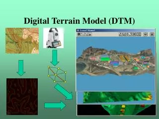
Digital Terrain Modeling. Photogrammetric Data Acquisition By M. Varshosaz. Photogrammetry : 3-D information from 2-D Imagery. DTM by Photogrammetry. DTM Generation. Computing Elevation. a) by (direct) “stereo geo-referencing”. (x,y) r. (x,y) l. (X,Y,Z). Photogrammetric Data Capture.

E N D
Digital Terrain Modeling Photogrammetric Data Acquisition By M. Varshosaz
Computing Elevation a) by (direct) “stereo geo-referencing” (x,y)r (x,y)l (X,Y,Z)
Photogrammetric Data Capture Based on stereoscopic interpretation of aerial and/or satellite imagery. Photogrammetric sampling techniques: Regular sampling patterns, Progressive sampling, Selective sampling, Composite sampling, Measuring contour lines, and
Photogrammetric DTM Generation Analytical Using optical electro-mechanical systems Operator sets up the model Using Grid measurement or contour following techniques Operator-Based; hence time consuming and error prone Digital Semi-automatic Similar to analytical techniques Still operator-based Automatic 7
Photogrammetric techniques (cont.) Automatic digital systems Aim To replace the operator by the Computer To improve speed Based on stereo-matching techniques 8
Digital Image Matching Objective: Automatic matching of conjugate points and/or entities in overlapping images. Applications include: Automatic relative orientation. Automatic aerial triangulation. Automatic DEM generation. Automatic ortho-photo generation.
Image matching techniques Area based Tries to match areas in one image with their corresponding areas in the other (patch matching) Feature based Relations between objects are used to match features 10
Area Based Matching Gray level distributions in small areas (image patches) in the two images of a stereo pair are matched. Similarity measures between the image patches can be computed using: Correlation coefficient. Least squares matching. Area based matching techniques are quite popular in photogrammetry.
Correlation Coefficient Assuming that: gl(x, y) is the gray value function within the template In the left image. gr(x, y) is the gray value function within matching window inside the search window in the right image. (nxm) is the size of the template and the matching windows. Then, the cross correlation coefficient (similarity measure) can be computed as follows:
Cross Correlation Factor The cross correlation factor might take values that range from -1 to +1. ρ= 0 indicates no similarity at all. ρ= -1 indicates an inverse similarity (e.g. similarity between the diapositive and the negative of the same image). ρ= 1 indicates a perfect match (the highest similarity possible).
Correlation Coefficient The cross correlation factor is computed for every possible position of the matching window within the search window. The position of the conjugate point is determined by the location of the maximum correlation factor. We will only accept correlation coefficients that are above a predetermined threshold (e.g. 0.5).
Correlation Matching Main disadvantage: We do not compensate for any geometric or radiometric differences between the template and the matching windows. Geometric differences will happen due to different scale and rotation parameters between the two images, foreshortening, etc. Radiometric differences will happen due to different illumination conditions. Need more sophisticated techniques
Problems Some problems that complicate the matching problem include: Scale differences between the two images. Different rotation angles between the two images. Tilted surfaces (foreshortening problem). Occlusions. Relief displacement (different background). Different illumination conditions between the two images (different gray values).