Download
1 / 44
500 likes | 624 Views
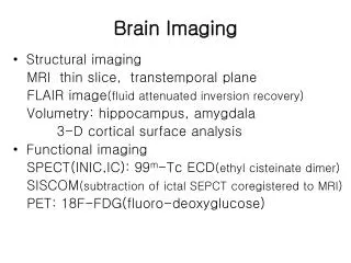
PRINCIPLES OF SPECT IMAGING - Ι. TYPES OF ACQUISITION, IMAGE STATISTICS AND DOSE REQUIREMENTS. George Fountos MSc, Ph.D, Radiation Physicist. 1. 2. 3. Planar. Tomographic. Acquisition. 4. Planar Imaging. Detector close to the patient

E N D
PRINCIPLES OF SPECT IMAGING - Ι TYPES OF ACQUISITION, IMAGE STATISTICS AND DOSE REQUIREMENTS George Fountos MSc, Ph.D, Radiation Physicist 1
Planar Tomographic Acquisition 4
Planar Imaging • Detector close to the patient • 3-D distribution of radioactivity is seen as a 2-D image • Projection images or projections 5
Disadvantage of planar imaging • Low Contrast A the radioactivity of a lesion Ao the radioactivity of the surrounded tissues 6
Advantage of Tomography • Removes overlay structures • Improves the image contrast 7
coronal sagittal transverse 8
Tomographic systems in Nuclear Medicine • SPECT (γ radiation) • PET(β+ radiation) 9
SPECT Acquisition • Rotation over 180° or 360° • Multiple planar images during its rotation 10
Acquisition Parameters • Appropriate collimation • Number of detectors • Matrix size • Arc of rotation • Projections per Arc of Rotation • Acquisition protocol • Orbit selection • Patient’s motion 11
1.Appropriate collimation The purpose of the collimator is to restrict the γ rays which reach the crystal to those which will form the required planar projection of the radionuclide distribution within the organ being imaged 12
Quality characteristics of a collimator Sensitivity Spatial resolution 1.Appropriate collimation 13
1.Appropriate collimation Spatial Resolution The measure of the ability of an imaging system, to separate the images of closely adjacent objects Rc the value of the spatial resolution, d the diameter of the holes, L the length of the holes, t the septal thickness. 14
1.Appropriate collimation Sensitivity Number of photons emitted by a uniform flat source passing through the collimator holes Sg the sensitivity, d the diameter of the holes, L the length of the holes, t the septal thickness. 15
1.Appropriate collimation When spatial resolution improves, sensitivity degrades and vice versa. 16
1.Appropriate collimation Collimator’s subcategories • Low energy – high resolution collimator (LEHR) • Low energy –general purpose collimator (LEGP) • Low energy – high sensitivity collimator (LEHS) • Middle energy - general purpose collimator (MEGP) • High energy – general purpose collimator (HEGP) 17
1.Appropriate collimation Parallel hole Collimator 18
1.Appropriate collimation Pinhole collimator Inverts and magnifies 19
1.Appropriate collimation Diverging collimator Minimizes the image 20
1.Appropriate collimation Converging Collimator Magnifies the object usually to a lesser degree than a pinhole collimator 21
1.Appropriate collimation Fan-Beam Collimator Fan-beam collimator has holes that converge in the transaxial direction (B) and maintain the conventional parallel hole geometry in the axial direction (A) A B 22
1.Appropriate collimation • In SPECT tomography, parallel hole collimators are used and according to the injected isotope they are LEHR, MEGP or HEGP. • Especially for brain tomographic imaging, to improve spatial resolution and sensitivity a fan beam collimator is the best choice. • Alternatively, in brain imaging using a gamma camera that is cut away on one side or a slant – hole collimator that can be angled to avoid the shoulder but still maintain close proximity to patient’s head, gives an advantage over a conventional parallel – hole collimator. 23
1.Appropriate collimation To achieve a twofold increase in the reconstructed resolution requires eight times the counts. (Resolution is a function of sensitivity to the third power) 24
2. Number of Detectors • One head camera: 360° orbit 25
Dual head camera: 2. Number of Detectors • 360° acquisition with only an 180° rotation of the gantry. • Examination is accomplished in the half of the expected time • Sensitivity increases twofold 26
2. Number of Detectors For Cardiac Tomographic Imaging To achieve the best sensitivity the two detectors must be fixed in a 90° configuration 27
2. Number of Detectors Triple head cameras • Increase 3X the sensitivity • Slight advantage for cardiac applications compare to single head systems, because the arc of rotation is only 120 ° per head 28
3. Matrix size Pixel = picture element • The smallest non invisible part of image • Single number representing the counts or image intensity 29
3. Matrix size The most common matrix size used in SPECT tomography: 64 X 64, or 128 X 128 30
3. Matrix size Sampling theory = at least 2 measurements across 1 cycle Nyquist frequency(critical or maximum frequency) f N = 1/ (2 x Pixel Size) 31
3. Matrix size • With current large FOV cameras, a 64 X 64 matrix size is preferred. • However, when the smallest object size approaches 1 cm, a 128 X 128 matrix size becomes more appropriate. 32
4.Arc of Rotation • Most SPECT acquisitions are accomplished with a 360° arc of rotation. • The one exception is cardiac imaging, in which a 180° acquisition is acceptable (from RAO to LPO position) with the myocardium in the near field of the detector. 33
4.Arc of Rotation • This position is used because photons traveling in a posterior direction from the myocardium must travel considerable distances through tissue. • Spatial resolution and sensitivity (owing to attenuation) are degraded in the posterior and right posterior oblique views. (In case of a dual head camera the detectors are fixed in a 90 ° configuration.) 34
5.Projections per Arc of Rotation Nyquist theory determines the number of projection views 120 views with a 360 degree acquisition 60 views with a 180 degree acquisition 35
5.Projections per Arc of Rotation Cardiac Tomography (Dual Head system): 32 images/detector in 180° orbit from RAO 45° to LPO 45° 36
6. Acquisition Protocol Step and shoot Continuous Both 3 different ways 37
Step and shoot acquisition: • (Method of choice) • The camera remains still during every step • Up to 30 sec/ step, 3° or 6° angle • Disadvantage: no counts can be obtained during the detector rotation between steps 6. Acquisition Protocol 38
6. Acquisition Protocol Continuous acquisition: (More complicated algorithm reconstruction ) The continuous radial orbit is divided into a certain number of projections ( usually 2°,3°,4°,6°) 39
7. Orbit Selection Circular or elliptic orbit? Changes of spatial resolution owing to the different angle of acquisition throughout the rotation 40
Circular orbit: resolution worsens Elliptical orbit: resolution improves 7. Orbit Selection 41
7. Orbit Selection Collimators in modern cameras are equipped with sensors that detect the presence of the patient and maintain the camera heads close to the patient as the orbit is completed 42
8. Patient’s motion • Less than ½ pixel is acceptable • To correct motion artifacts, it is important to detect the myocardium center through image projections and compare the data with the expected information if patient was completely still 43
Thank you 44