Download

1 / 16
200 likes | 1.05k Views
MOCT MAGNETO OPTICAL CURRENT TRANSFORMER. PRINCIPLE OF MOCT. The Magneto-Optical current transformer is based on the Faradays effect. . Generally, this phenomenon can be described as follows: ‘ ’ is the Faraday rotation angle, ‘V’ is the Verdet constant of magneto-optical material,

E N D
PRINCIPLE OF MOCT • The Magneto-Optical current transformer is based on the Faradays effect. .
Generally, this phenomenon can be described as follows: • ‘’ is the Faraday rotation angle, • ‘V’ is the Verdet constant of magneto-optical material, • ‘B’ is the magnetic flux density along the optical path, • ‘l’ is the optical path. = V dl (1)
Eq. (1),can be rewritten according to Ampere’s law as: =nVI (2) • ‘I ‘is the current to be measured, • ‘’ is the permeability of the material, • ‘n’ is the number of turns of the optical path.
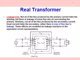
The typical application of the Faraday effect to an MOCT is clear from fig.
The output optical signals from the analyzer can be described as, P1 = (P0 / 2) (1 + Sin 2 ) (3) P2 =(P0 / 2) (1 - Sin 2 ) (4) • P0 is the optical power from the light source, • is the Faraday rotation angle, • P1 and P2 are the optical power delivered by the detectors.
DESIGN OF MOCT • The following fig shows the structure of MOCT.
The two halves can be assembled around the conductor. • The rotation angles from the two halves of the sensor Fig(a) are added up in the signal processing unit so that the total rotation angle (1+2 ) is the same as the rotation angle from the optical path shown in Fig(b), which is two turns around the conductor.
Fig shows the structure of the housing for the clamp-on MOCT.
MAGNETO OPTICAL SENSOR • Almost all transparent material exhibits the magneto-optical effect or Faraday Effect. • In the MOCT, from Eq (2), the total internal rotation angle is, 1+ 2 2VI (5) • Where I is the current to be measured, • = 4 x 10⁻⁷ H/m, • V=7.7 x 10² degrees/Tm at a wavelength of 820nm, • Therefore = 1.9 degrees/ KA.
ADVANTAGES OF MOCT • No fires and explosions. • No need to use metallic wires to transfer the signal. • Immune to electromagnetic interference. • Wider frequency response and larger dynamic range. • Low voltage outputs.
DISADVANTAGES OF MOCT • Temperature and stress induced linear birefringence causes error and instability. • Insufficient accuracy.
APPLICATIONS • The MOCT is designed to operate in a transparent manner with modern electronic meters and digital relays. • The MOCT system satisfies current sensoring needs for revenue metering or protective relaying.
CONCLUSION • Magneto optical current transducer eliminates many of the drawbacks of the conventional current transformers. • By applying Faraday’s principle this transducer provides an easier and more accurate way of current measurement. This MOCT is widely used in power systems and substations nowadays. • A new trend is being introduced, which known as OCP based on adaptive theory.