Download
1 / 44
440 likes | 521 Views
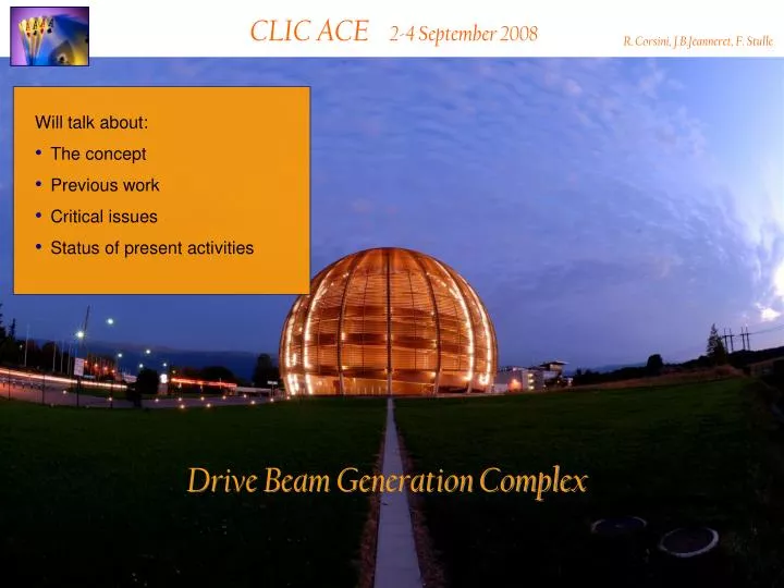
CLIC ACE 2-4 September 2008. R. Corsini, J.B.Jeanneret, F. Stulle. Will talk about: The concept Previous work Critical issues Status of present activities. Drive Beam Generation Complex. 650 Klystrons low frequency high efficiency. 143000 Accelerating Structures

E N D
CLIC ACE 2-4 September 2008 R. Corsini, J.B.Jeanneret, F. Stulle • Will talk about: • The concept • Previous work • Critical issues • Status of present activities Drive Beam Generation Complex
650 Klystrons low frequency high efficiency 143000 Accelerating Structures high frequency high gradient Power stored in electron beam Power extracted from beam in resonant structures Electron beam manipulation Short RF Pulses PA = P0 N1 tA = t0 / N2 nA = n0 N3 Long RF Pulses P0 ,n0 ,t0 What does the RF Power Source do ? The CLIC RF power source can be described as a “black box”, combining very long RF pulses, and transforming them in many short pulses, with higher power and with higher frequency
Delay loop 2 gap creation, pulse compression & frequency multiplication Transverse RF Deflectors Combiner ring 3 pulse compression & frequency multiplication Combiner ring 4 pulse compression & frequency multiplication Drive Beam Decelerator Sector (24 in total) Power Extraction Drive beam time structure - final Drive beam time structure - initial 240 ns 240 ns 5.8ms 140mstotal length - 24 24 sub-pulses - 4.2 A 2.4 GeV - 60 cm between bunches 24 pulses – 100 A – 2.5 cm between bunches Drive Beam Accelerator efficient acceleration in fully loaded linac RF Power Source Layout
Full beam-loading acceleration in TW sections No High current beam most of RF power (≥ 95%) to the beam RF Power Source “building blocks” RF to load RF in No beam “short” structure - low Ohmic losses
P , n 0 0 2 P , 2 ´ ´ n 0 0 P , n 0 0 Deflecting Field Beam combination/separation by transverse RF deflectors RF Power Source “building blocks” Transverse RF Deflector, n 0
2 1 RF Power Source “building blocks” Counter propagation from central complex Instead of using a single drive beam pulse for the whole main linac, several (NS = 24) short ones are used. Each one feed a 800 m long sector of TBA. decelerator sector main linac main beam pulse pulse 2 pulse 1 From central complex (DLDS-like system) Counter-flow distribution allows to power different sectors of the main linac with different time bins of a single long electron pulse. The distance between pulses is 2 LS = 2 Lmain/NS. The initial drive beam pulse length is equal to 2 Lmain= 140 ms/c.
Phase coding How to “code” the sub-pulses Sub-Harmonic Bunching n0 / 2 Combination scheme 180 phase switch Acceleration n0 Deflection n0 / 2 even buckets • Delay Loop odd buckets • RF deflector Gap creation & first multiplication 2 Ldelay = nl0 = c Tsub-pulse
Streak camera – 500 ps/mm 1 8 666 ps 8.5 · 666 ps = 5.7 ns satellite main Fast phase switch from SHB system (CTF3) 3 TW Sub-harmonic bunchers, each fed by a wide-band TWT … or use a laser + photo-injector
injection line 1st turn 2nd septum 1st deflector 2nd deflector local inner orbits lo RF deflector field 4rd 3rd lo/4 RF injection in combiner ring (factor 4 for simplicity) Cring = (n + ¼) l
Status (derived from Daniel`s talk) • A complete zero-order conceptual design on the drive beam complex has been published in ’99 (Yellow report CERN 99-06). Since then, the parameters changed (in general in a favorable direction) and some of the concepts evolved and/or were tested in CTF3. • It is now time to fully review all components. • Some conceptual work on overall drive beam complex layout remains to be done • - drive beam phase stability, see later • Drive beam injector • - CTF3 a good example, RF injector preferred (no satellites) – to be tested in CTF3 as well • Drive beam accelerator • - design existed for previous parameter set, needs to be redone (no major problems) • Delay loop and combiner rings • - design needs to be revisited, modified and evaluated • - this is a critical item • Bends into long transfer line • - does not exist but should be relatively easier than other bends • Transfer lines and turn-around into decelerator and compressor/feedback • - baseline exists • Drive beam decelerator • - design exists, some improvements, cost driver
Injector 140 4.2 7.8 L. Rinolfi LC ’99 Workshop Scaling from CTF3 & new parameters reassuring, but satellites problem, stability…
Injector – RF gun option PHIN RF gun PHIN test stand in former CTF II CTF3 thermionic injector • Smaller transverse emittance • Shorter bunches, no energy tails • No satellites • Issues (to be tested in CTF3) • High charge, long pulse laser… • Stability RF gun implementation in CTF3
CTF3 basically OK In CTF3 ~ 1mm from injector Need full study (phase stability) Accelerator R. Corsini LC ’99 Workshop No big problems expected, but design needed for realistic start-to-end simulations (especially longitudinal gymnastics/phase stability)
favorable param. scaling CTF3 to be checked CTF3 Delay Loop & Combiner Rings R. Corsini LC ’99 Workshop
B. Jeanneret work-in-progress ~ +/- 0.2 mm /arc at +/- 2% ~ +/- 0.3 mm /arc at +/- 2% lattices, 2nd order isochronicity, chrom. control R. Corsini CERN 99-06
Energy loss from SR and CSR sZ= 2 mm, Qb = 7.8 nC ‘99 parameters Both rings -r= 10 m - 27 m total SR CSR Shielded (h=20mm) • NB: I have kept the same sZ in the rings as the old parameter set – now we need only a factor 2 in final compression • can accept more longitudinal phase space distortion • will be less sensitive to energy variation for drive beam phase stability
Another ring issue – transverse stability in the RF deflectors D. Schulte – R. Corsini ‘99 parameters OK in CTF3, but vertical polarity (trapped) critical – should be OK with damping or couplers Optimum ring tune
Old & last 30 GHz parameters 2005 - CLIC Note 627 August 2008
B. Jeanneret Task list • 1) INJECTION LINAC • a. RF Structures • b. Linear optics • c. Collective effects • d. dE/dz correlation for later compression • 2) BUNCH STRUCTURE to build trains (rise time / flat section / Fall time) • 3) DELAY LOOP • a. Isochronous & achromatic optics, beta-beating control • 4) COMBINER RINGS • a. Isochronous & achromatic optics, beta-beating control • 5) RF DEFLECTORS FOR DL, CR1, CR2 • 6) TRANSFER LINE DOWN TO TUNNEL • a. Optics • b. layout • 7) FINALIZE THE LONG TRANSFER LINE • a. Optics & layout • b. Kick-out and matching to turnarounds • c. Beam-based alignment • 8) TURN-AROUND TO DECELERATOR • a. Matching • b. Layout & compatibility with other beam lines • 9) EXTRACTION OF SPENT BEAM after decelerator • a. Optics • b. Compatibility with other beam lines • 10) DUMP CONCEPTUAL DESIGN • 11) TIMING Drive Beam / Main Beam • 12) ALL THE ABOVE • a. Transverse feed-back • b. Longitudinal feed-back • c. Magnet specification and inventory (at least for cost) • d. Specification for vacuum • e. Specification for instrumentation • f. Machine protection • g. Collimation
B. Jeanneret DB long transfer line : simple optics but 21 km long Issues : • Optics • Parasitic dispersion + |dp|=2% => emittance dilution • Logistics • Beam line suspended to the ceiling • Light & transversely thin magnets preferred • Cost & power • Weak magnets preferred • Collective effects • Trains : 100 A , 73 m long • Strong transverse multi-bunch resistive wake-fields • Ions => detuning & instabilities Deserves global optimisation
10.02 deg 1m 2.5m 1m 10m 5.53deg 1m 8m 0.75m 20m F. Stulle Bunch Compressor Chicane 10 m Turn Around Loop 77 m = 1x 60deg arc + matching + 3x 80deg arc Bunch Compressor Chicane 20 m Layout of final BCs & turn-around loop Phase measurements
F. Stulle Design Considerations / Constraints - BCs Bunch Compressors BC1 and BC2: • BC1 is not only a bunch compressor, but is also used to convert an incoming energy jitter into a measurable phase jitter • for the energy jitter measurement its R56 should not be too small: • the phase error measured in front of the loop is corrected in BC2 by changing the path length of the bunches • its R56, i.e. the bending angles, should be large enough to allow the usage of weak correction kickers: • the influence of ISR is small due to the huge beam emittance and the rather low electron energy • CSR (transverse) is also rather easy to control due to the huge beam emittance
F. Stulle Design Considerations / Constraints - TALs Turn Around Loop: • the turn around loop has to be achromatic and should be isochronous • it has to be compact and simple since 2 x 24 loops are required • the R56(s) should stay close to zero, since the bunch has an energy chirp it might be compressed to short lengths, i.e. it might radiate a lot CSR • this is the main complication for the lattice design, a trade-off has to be made between R56(s), T566(s) and chromaticity • the influence of ISR is small due to the huge beam emittance and the rather low electron energy • CSR (transverse) is also rather easy to control due to the huge beam emittance
F. Stulle Turn Around Loop lattice
F. Stulle Simulation Results, 1D CSR longitudinal phase space CSR in Loop T566 in Loop transverse, hor phase space initial final
CONCLUSIONS • The last extensive and coherent study of the drive beam complex has been completed in ’99 (Yellow report CERN 99-06). • Since then, the parameters changed (many times). • New parameters are in most respects much more favorable than old ones. • Still, it is now time to fully re-design and assess all components, including the ones neglected at the time. Work just started. • The experience accumulated since then in CTF3 extremely useful. It relieved many worries we had, and raised a few new ones. Past and future studies in CTF3 are a valuable input to steer the new studies. • Some of the critical issues (beam power and losses management, machine protection, stability...) need strong effort – scarce at present. This is especially important since they are addressed only partially in CTF3.
Drive beam current & energy trade-off Since the power per sector is fixed, the product Ibeam Ebeam is constant For: is good to haveTransverse beam stability in decelerator high current, large aperture, long PETSDrive beam combination in rings small current, high energy (but below about 2.5 GeV)
Drive beam energy limits Several issues can put an upper limit to the beam energy in the combiner rings: • Too high field in magnets not an issue (long rings – long RF pulse length) • Synchrotron radiation: • Energy loss not limiting • Power loss in vacuum chamber potential limit • Energy spread & emittance increase negligible • Coherent synchrotron radiation • Beneficial effect • Deflectors • Higher power for given angle • Constant power from damping of real emittance → neutral
CTF3 – Layout DELAY LOOP 4 A – 1.2 ms 150 Mev COMBINERRING DRIVE BEAM LINAC 30 A – 140 ns 150 Mev CLEX CLIC Experimental Area 10 m
recombination x 4 recombination x 2 bunch length control bunch compression fully loaded acceleration structures 12 GHz phase-coding PETS on-off deceleration stability two-beam acceleration structures 30 GHz CTF3 – R&D Issues - where R1.1 – structures R1.2 – DB generation R1.3 – PETS on-off R 2.1 – structure materials R 2.2 – DB decelerator R 2.3 – CLIC sub-unit
2008 structures 12 GHz PETS on-off deceleration stability two-beam acceleration structures 30 GHz CTF3 – R&D Issues - when recombination x 4 recombination x 2 bunch length control bunch compression fully loaded acceleration phase-coding 2009 2010
Dipole modes suppressed by slotted iris damping (first dipole’s Q factor < 20) and HOM frequency detuning RF pulse at structure input MKS05 MKS03 MKS06 MKS07 1.5 µs beam pulse RF pulse at structure output Spectrometer 4 Spectrometer 10 analog signal damping slot SiC load Full beam loading acceleration stability - efficiency Measured RF-to-beam efficiency 95.3 % Theory 96% (~ 4 % ohmic losses)
Streak camera image satellite main 1 8 666 ps 8.5 · 666 ps = 5.7 ns Fast phase switch from SHB system phase coding 3 TW Sub-harmonic bunchers, each fed by a wide-band TWT
Satellite control, RF gun option • Better emittance • Shorter bunches • No satellites • Lower current
F. Stulle Simulation Results, 1D CSR CSR in Loop T566 in Loop longitudinal phase space transverse phase space initial final