Download
1 / 24
240 likes | 249 Views
Industrial training Electrical Loco Shed, Ghaziabad. Name : Shreyashkar Singh ABES engineering college EEE 4 th year (1003221092 ) shreysng@gmail.com. I NTRODUCTION. ESTABLISHMENT

E N D
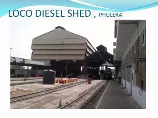
Industrial training Electrical Loco Shed, Ghaziabad Name : ShreyashkarSingh ABES engineering college EEE 4th year (1003221092) shreysng@gmail.com
INTRODUCTION ESTABLISHMENT > Electric Loco Shed was set in 1976 by Railway Electrification Organisation (8910 SQ. MTRS). > It’s main purpose is of maintenance of WAP1,WAP4,WAP5,WAP7 ,WAG5, WAM4 engines. INITIAL COST Rs. 1.5 (IN CRORES) PRESENT LOCO HOLDING 185
TYPES OF LOCOS HOLDING- [gauge] [power] [load] [series] 1. WAP1 (Traction Motors:4,575kW ,18 coaches) 2. WAP4 (Traction Motors- 6,630 kW, 750V, 26 coaches ) 3. WAP5 (Traction Motors-3phase squirrel-cage induction motors(1150kW, 2180V). 4. WAP7 (Traction Motors- 3phase squirrel-cage induction motors(850 kW, 2180V). 5. WAG5 (Haulage Capacity-2375t 6. WAM4 (Traction Motors-6, 575kW, 750V, Hauling capacity-2010t
INTRODUCTION • TRACTION Driving forward of vehicle is called traction and the system, which employ this type of mechanism is called as traction system. Classified broadly into two groups namely: 1. Non Electric Traction System. 2. Electric Traction System. >Electric Traction means a Locomotion in which the driving force is obtained from electric motors. >For Traction purpose 3-phase induction motor and DC series motor are used and both have high starting torque provide high speed acceleration.
TYPES OF ELECTRIC TRACTION SYSTEM • DC Traction • AC Traction DCTRACTION • DC traction units uses direct current drawn from overhead line. • DC traction units uses 600v-750v DC voltage range . • The low-voltage,serieswound,direct current motor is well suited to railroad traction,being simple to construct and easy to control.
ACTRACTION • AC Traction units draw alternating current from an overhead line. • Typical voltages used are- • 15kV /25kV AC,50Hz • Fewer substations are required and the lighter overhead current supply wire can be used. • Reduced capital cost of electrification
Components of an ac locomotive • CATENARY:- This is the Over head Wire of Special Cross section of area. • PANTOGRAPH:- This is a device used for collecting current from the catenary. • CIRCUIT BREAKER:- To disconnect the engine from the line side in case of some fault. • RECTIFIERS:- Conversion of AC power into DC power. • SMOOTHING REACTORS:- Any ripple found on the output side of the rectifier are eliminated bythis fitted after the rectifier. • TRANSFORMER:- It is installed in locomotive for step down the voltage according to the requirement of motor.
Pantograph A pantograph is a device that collects electric current from overhead lines for electric trains or trams. It is spring loaded and pushes a contact shoe up against the contact wire to draw the electricity needed to run the train. Pantographs are typically operated by compressed air from the vehicle's braking system, either to raise the unit and hold it against the conductor .
Brakes Mainly two types of brakes are used- 1. Air Brake System 2. Regenerative Brake System.
1.Air Brake System • This braking systems use compressed air as the force to push blocks on to wheels or pads on to discs. • In this system three main positions are used in controlling the loco. • Application Position • Release Position • Lap Position
2.Regenerative Brake system • During braking, the traction motor connections are altered to turn them into electrical generators. • The motor fields are connected across the main traction generator and the motor armatures are connected across the load. • The rolling locomotive or multiple unit wheels turn the motor armatures, and the motors act as generators, either sending the generated current back into the supply.
Traction Motor In electric locos mainly squirrel cage, 3-phase Induction Motor is used. Nose suspended, axle hung type traction motor is used.
Nose-Suspended type traction motor Motor is mounted in the bogie frame supported partially by the axle which it drove and partially by the bogie frame. The motor case is provided with a "nose" which rested on a bracket fixed to the frame of the bogie.
WHEEL: Wheels are manufactured of cast steel. Railway wheels sit on the rails without guidance. the flanges should not touch the rails. The wheel tire is coned . Rail head slightly curved as shown in the diagram.
ADVANTAGE OF ELECRICAL LOCO • High power-to weight ratio. • Fewer Locomotive • Fast Acceleration • Higher limit of speed • Higher hauling capability • No carbon emission • Less noise pollution • Maintenance cost is 50% of that for steam engine. • Steam engine requires two hours for heat up whereas electric engine start within moment. • High torque motor are used in electric traction.
DISADVANTAGES • Significant capital cost of electrification. • Maintenance cost is high. • Overhead wires further limit the clearance in tunnel. • Railway traction need immune power, with no cuts.