Download
1 / 42
420 likes | 430 Views
CSCI260 Database Applications. Data Modeling and the Entity-Relationship Model. Chapter Four. Chapter Objectives. Learn the basic stages of database development Understand the purpose and role of a data model Know the principal components of the E-R data model

E N D
CSCI260 Database Applications Data Modeling and theEntity-Relationship Model Chapter Four
Chapter Objectives • Learn the basic stages of database development • Understand the purpose and role of a data model • Know the principal components of the E-R data model • Understand how to interpret both traditional and UML-style E-R diagrams • Learn to construct traditional E-R diagrams • Know how to represent 1:1, 1:N, N:M, and binary relationships with the E-R model
Chapter Objectives (continued) • Know how to represent recursive relationships with the E-R model • Understand two types of weak entities and know how to use them • Learn how to create an E-R diagram from source documents
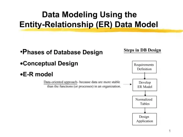
Three Stages of Database Development • Requirements Stage • Design Stage • Implementation Stage
The Requirements Stage • Sources of requirements • User Interviews • Forms • Reports • Queries • Use Cases • Business Rules
Requirements Become theE-R Data Model • After the requirements have been gathered, they are transformed into an Entity Relationship (E-R) Data Model • E-R Models consist of • Entities • Attributes • Identifiers • Relationships
Entities • An entity is something that users want to track • CUSTOMER • PROJECT • EMPLOYEE • STUDENT
Instance versus Classes • An entity class is a description of the structure and format of the occurrences of the entity • An entity instance of a specific occurrence of an entity class
CUSTOMER CustID CustName Entity Class 12735 Smither, Inc 78124 Jackson Co. Two Entity Instances Instance versus Classes
Attributes • Entities have attributes that describe the entity’s characteristics • ProjectName • StartDate • ProjectType • ProjectDescription • Attributes have a data type and properties
Identifiers • Entity instances have identifiers • An identifier will identify a particular instance in the entity class • SocialSecurityNumber • StudentID • EmployeeID
Identifier Types • Uniqueness • Identifiers may be unique or nonunique • If the identifier is unique, the data value for the identifier must be unique for all instances • Composite • A composite identifier consists of 2 or more attributes • E.g., OrderNumber & LineItemNumber are both required
Relationships • Entities can be associated with one another in relationships • Relationship degree defines the number of entity classes participating in the relationship • Degree 2 is a binary relationship • Degree 3 is a ternary relationship
LOCKER EMPLOYEE Degree 2 Relationship - Binary
DEALER MODEL MAKE Degree 3 Relationship - Ternary
One-to-OneBinary Relationship • 1:1 (one-to-one) • A single entity instance in one entity class is related to a single entity instance in another entity class
LOCKER EMPLOYEE 1:1 One-to-OneBinary Relationship • An employee may have no more than one locker; and • A locker may only be accessible by one employee
DEPARTMENT EMPLOYEE 1:N One-to-ManyBinary Relationship • An employee may only work for one department; and • A department has several employees
SKILL EMPLOYEE N:M Many-to-ManyBinary Relationship • An employee may have several skills; and • A particular skill may be held by several employees
EMPLOYEE 1:N One-to-ManyUnary Relationship • An employee may be managed by one other employee • A employee may manage several employees
EMPLOYEE 1:N One-to-ManyUnary Relationship • An employee may be managed by one other employee • A employee may manage several employees
Cardinality • Each of the three types of binary relationships shown above have different maximum cardinalities • Minimum cardinalities also exist. These values typically assume a value of Mandatory (one) or Optional (zero)
LOCKER EMPLOYEE | 1:1 0 One-to-One Binary Relationship with Minimum Cardinality • An employee must have one locker; and • A locker may be accessible by one or zero employees
EMPLOYEE DEPENDENT | 1:N 0 Weak Entity • A weak entity is an entity that cannot exist in the database without the existence on another entity • For example, an employee’s dependents cannot exist in a database without the employee existing in the database
BUILDING APARTMENT | 1:N 0 ID-Dependent Weak Entities • An ID-Dependent weak entity is a weak entity that must include the identifier of its parent entity as part of its composite primary key
PATIENT PERSCRIPTION | 1:N 0 Weak Entity Identifier:Non-ID-dependent • A non-ID-dependent weak entity may have a single or composite identifier, and the identifier of the parent entity will be a foreign key
PROJECT ASSIGNMENT | 1:N 0 Weak Entity Identifier:ID-Dependent • An ID-dependent weak entity has a composite identifier • The first part of the identifier is the identifier for the strong entity • The second part of the identifier is the identifier for the weak entity itself
Weak Entity Relationships • The relationship between a strong and weak entity is termed an identifying relationship if the weak entity is ID-dependent • The relationship between a strong and weak entity is termed a non-identifying relationship if the weak entity is non-ID-dependent
Unified Modeling Language Entity-Relationship Diagrams • Unified Modeling Language (UML) is a set of structures and techniques for modeling and designing object-oriented programs (OOP) and applications
ENTITY_NAME List of Attributes Identifier Unified Modeling Language Entities
1..1 Mandatory One 0..1 Optional One 0..* Optional Many 1..* Mandatory Many Unified Modeling Language Relationships
EMPLOYEE DEPARTMENT EmployID EmployName Phone DeptID DeptName Location 0..* 1..1 EmployID is identifier DeptID is identifier UML E-R Diagram Example • An employee must report to one department; and • A department may have zero or many employees
EMPLOYEE DEPENDENT EmployID EmployName Phone DepSSN DepName DepAge 1 0..N EmployID is identifier DepSSN is identifier UML Weak Entity
Data Modeling and theEntity-Relationship Model End of Presentation on Chapter Four