Download
1 / 17
180 likes | 356 Views
Arithmetic- Logic Units (ALUs). The four-bit adder. The basic four-bit adder always computes S = A + B + CI But by changing what goes into the adder inputs A, B and CI, we can change the adder output S This is also what we did to build the combined adder-subtractor circuit.

E N D
The four-bit adder • The basic four-bit adder always computes S = A + B + CI • But by changing what goes into the adder inputs A, B and CI, we can change the adder output S • This is also what we did to build the combined adder-subtractor circuit
It’s the adder-subtractor again! • Here the signal Sub and some XOR gates alter the adder inputs • When Sub = 0, the adder inputs A, B, CI are Y, X, 0, so the adder produces G = X + Y + 0, or just X + Y • When Sub = 1, the adder inputs are Y’, X and 1, so the adder output is G = X + Y’ + 1, or the two’s complement operation X - Y
The multi-talented adder • So we have one adder performing two separate functions • “Sub” acts like a function select input which determines whether the circuit performs addition or subtraction • Circuit-wise, all “Sub” does is modify the adder’s inputs A and CI
Modifying the adder inputs • By following the same approach, we can use an adder to compute other functions as well • We just have to figure out which functions we want, and then put the right circuitry into the “Input Logic” box
One way: Set A = 0000, B = X, and CI = 1 A = 1111 (-1), B = X, CI = 0 A = 0000, B = X, CI = 0 Some more possible functions • We already saw how to set adder inputs A, B and CI to compute either X + Y or X – Y • How can we produce the increment function G = X + 1? • How about decrement: G = X - 1? • How about transfer: G = X? This is almost the same as the increment function!
Table of arithmetic functions • Here are some of the different possible arithmetic operations • We’ll need some way to specify which function we’re interested in, so we’ve randomly assigned a selection code to each operation
Mapping the table to an adder • This second table shows what the adder’s inputs should be for each of our eight desired arithmetic operations • Adder input CI is always the same as selection code bit S0 • B is always set to X • A depends only on S2 and S1 • These equations depend on both the desired operations and the assignment of selection codes
Building the input logic • All we need to do is compute the adder input A, given the arithmetic unit input Y and the function select code S (actually just S2 and S1) • Here is an abbreviated truth table: • We want to pick one of these four possible values for A, depending on S2 and S1
Primitive gate-based input logic • We could build this circuit using primitive gates • If we want to use K-maps for simplification, then we should first expand out the abbreviated truth table • The Y that appears in the output column (A) is actually an input • We make that explicit in the table on the right • Remember A and Y are each 4 bits long!
Primitive gate implementation • From the truth table, we can find an MSP: • Again, we have to repeat this once for each bit Y3-Y0, connecting to the adder inputs A3-A0 • This completes our arithmetic unit Ai = S2Yi’ + S1Yi
1011 AND 1110 1010 1011 OR 1110 1111 1011 XOR 1110 0101 Bitwise operations • Most computers also support logical operations like AND, OR and NOT, but extended to multi-bit words instead of just single bits • To apply a logical operation to two words X and Y, apply the operation on each pair of bits Xi and Yi: • We’ve already seen this informally in two’s-complement arithmetic, when we talked about “complementing” all the bits in a number
Defining a logic unit • A logic unit supports different logical functions on two multi-bit inputs X and Y, producing an output G • This abbreviated table shows four possible functions and assigns a selection code S to each • We’ll just use multiplexers and some primitive gates to implement this • Again, we need one multiplexer for each bit of X and Y
Our simple logic unit • Inputs: • X (4 bits) • Y (4 bits) • S (2 bits) • Outputs: • G (4 bits)
Our ALU function table • This table shows a sample function table for an ALU • All of the arithmetic operations have S3=0, and all of the logical operations have S3=1 • These are the same functions we saw when we built our arithmetic and logic units a few minutes ago • Since our ALU only has 4 logical operations, we don’t need S2. The operation done by the logic unit depends only on S1 and S0
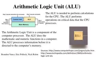
4 Cout should be ignored when logic operations are performed (when S3=1). 4 4 4 4 The arithmetic and logic units share the select inputs S1 and S0, but only the arithmetic unit uses S2. A complete ALU circuit The / and 4 on a line indicate that it’s actually four lines. • G is the final ALU output. • When S3 = 0, the final output comes from the arithmetic unit. • When S3 = 1, the output comes from the logic unit.
4 4 4 4 The completed ALU • This ALU is a good example of hierarchical design • With the 12 inputs, the truth table would have had 212 = 4096 lines. That’s an awful lot of paper. • Instead, we were able to use components that we’ve seen before to construct the entire circuit from a couple of easy-to-understand components • As always, we encapsulate the complete circuit in a “black box” so we can reuse it in fancier circuits.