Download
1 / 10
120 likes | 182 Views
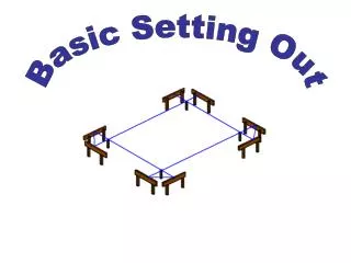
SETTING OUT. Horizontal Angles. Horizontal Angles. Ensure instrument is set to measure angles in the appropriate direction. ( refer to operators manual) Unclamp both vertical and upper horizontal clamps. Ensure lower horizontal clamp (if fitted) is locked .

E N D
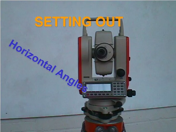
SETTING OUT Horizontal Angles
Horizontal Angles • Ensure instrument is set to measure angles in the appropriate direction. ( refer to operators manual) • Unclamp both vertical and upper horizontal clamps. • Ensure lower horizontal clamp (if fitted) is locked. • Use target finder to locate reference target station keeping one hand on horizontal clamp. Clamp in smooth operation when target located. • Look through telescope and bring target into focus. Start with focussing ring turned fully one way then will avoid “missing” focal point. • Use Horizontal and Vertical tangent screws to bring stadia lines over target. • Ensure that target is vertical or use the lowest point visible.
Set angle • Zero set instrument (refer to manual) • Unclamp horizontal clamp and move instrument round until digital read out is within 1 of desired angle. • Clamp horizontal and use tangent screw to adjust digital read out to desired angle. • Be aware of accuracy of instrument. (typically 5”) • Give arm signals to assistant to locate ranging rod in desired direction. • Target the point of the ranging rod.
2nd 3rd 5th 1st 4th Assistant’s role • Stretch out tape ( or accurately pace) in viewing direction • Hold ranging rod vertically at approx set out distance. • Follow arm signals from engineer • NOTE: Do not move rod haphazardly. Bisect the difference between rod movements. This will very quickly get you to the correct direction.
Assistant’s role – Taped measurement • Replace ranging rod with stake – hold stake centre-line adjacent to correct measurement on tape and drive stake in vertically. • (ensure that the tape is held approx level OR use calculated sloping distance) • Place tape on stake head and mark, with a pencil, an arc of radius equal to setting out distance. (slope corrected if necessary)
Assistant’s role – Taped measurement • Move nail across arc and follow engineers arm signal to get correct direction. • Mark nail position to make a cross with previously drawn arc. • At this point the Engineer will transit the telescope and repeat the angle setting out in the opposite face. • Follow the engineers arm signals and then mark a second cross on the previously drawn arc • Bisect the difference between the two crosses and drive in a nail vertically
Assistant’s role – using EDM and Reflector • Once on correct line, replace ranging rod with reflector prism on short spike. • Set spike to approx distance and follow engineers arm signals for moving back or forward. (Bisect difference as for transverse movements) • Mark ground and drive in vertically a stake at this point. • Repeat location on stake head and mark with pencil. • At this point the Engineer will transit the telescope and repeat the angle setting out in the opposite face • Locate and mark a second point on the stake head. • Drive in a nail half way between the two crosses. • Check distance to the nail.
Face I Face II Nail centred between two marks arc Face I and Face II • Once the engineer has located the stake out point in face I setting he must repeat the same operation in the face II setting. • This eliminates any collimation errors due to the vertical axis not being truly perpendicular to the trunnion axis.
Final check • Once a mark has been set out, before transiting the telescope, the engineer should return the instrument to target the reference station and check if the digital display again reads zero. • This should be repeated on both faces.