Download
1 / 24
330 likes | 883 Views
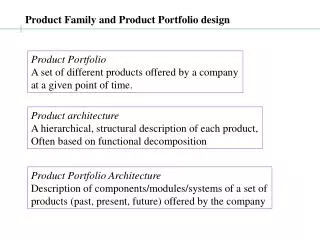
Thermoforming Tooling and Product Design. TEC 315 Dr. Lou Reifschneider. Vacuum Forming. Fig.14.1 Plastics by A. Brent Strong. Typical female mold and wall thickness variation. Fig. 25 Practical Thermoforming by John Florian. Wall thickness variation for simple vacuum forming.

E N D
ThermoformingTooling and Product Design TEC 315 Dr. Lou Reifschneider
Vacuum Forming Fig.14.1 Plastics by A. Brent Strong
Typical female mold and wall thickness variation Fig. 25 Practical Thermoforming by John Florian
Wall thickness variation for simple vacuum forming Fig.3.1 Understanding Thermoforming by James Throne
Drape Forming Fig.14.6 Plastics by A. Brent Strong
Typical male mold and wall thickness variation Fig. 26 Practical Thermoforming by John Florian
Plug Assist Forming Fig.14.3 Plastics by A. Brent Strong
Basic Forming Set-ups and Tooling used for each • Straight Vacuum – female mold • Drape Forming – male mold • Plug-assist: female mold with plug (plug helps avoid thinning of sheet in bottom of mold cavity) • Web-assist: typically drape-style mold with features that require mechanical aid to avoid web forming
Basic TF Mold Nomenclature Draft Air Holes Lip Female Mold Feet Base Plate Vacuum Molded Part Florian, Practical Thermoforming
TF Mold Basics (1/4) • Male or Female mold? Plug assist, etc.. • … depends on product needs: wall thickness control and surface detail. • Texture on mold side. Do not want texture? (scroll marks) make used side away from mold. • Shrinkage allowance • ABS ~ 0.007 in/in • PS ~ 0.006 in/in • PE ~ 0.025 in/in
TF Mold Basics (2/4) • Mold Material - production run? • Short - wood, epoxy, uPET, plaster • Long - aluminum (cast) with cooling lines • Only strong mat’l for pressure forming!! • Make pattern - cast epoxy or plaster, or FDM. Cast pattern out of aluminum. • CNC mill mold directly (easier for male mold geo.) • Cooling - cast lines in place or drill cooling lines
TF Mold Basics (3/4) • Vent Holes - • place at last areas to draw down, • small hole that is back-drilled (aids air flow and easier to machine), • Hole size = f(E(temp), pressure, thickness) • No. of holes = g(trapped volume/form time, air speed limit (sonic)) • more needed for pressure forming because of the speed of forming.
TF Mold Basics (4/4) • Draft: 1° to 10° - depends on mold design • Draw Ratio = Depth of Part Feature/Width of Part Feature • Female molds DR max ~ 2 • Male molds DR (or plug assist) ~ 7 • Estimate final thickness with Area Ratio: Area Ratio = Area of Part / Area of Sheet used to Form Part
Vent hole detail (typical) Back-drilled vent hole Fig.14.11 Plastics by A. Brent Strong
Vacuum system schematic Fig.4.7 Understanding Thermoforming by James Throne
TF Product Design Overview • Draft mold for mold release (more is better) ~ 1° for female mold (straight vacuum) ~ 4° for male mold (drape forming) • Increase draft with texture: + 1° for each 0.0002 inch of texture depth • Generous radii: R > 4 x local sheet thickness • Smaller radii possible with hotter sheet or faster forming times. • Ribs, corrugations, cones: stiffen walls
TF Product Forming Overview • Male mold vs. Female mold • Male mold cheaper to make • Product design implications: • more draft Male = 4 to 10°, Female = 1 to 5° • Pressure forming (competes with IM) • mold and pressure box must be locked together (expensive TF tooling but …) • ~20% lower tooling cost than IM and ~1/2 lead time compared to IM TIME IS MONEY!!
Troubleshooting Product Defects Primary Causes of Defects: Processing - temperatures, vacuum Mold design - draft, tool features: protrusions, undercuts Material - moisture, impurities
TF Troubleshooting:Selected Problems (1/2) Problem/Cause/Cure • Incomplete molding • processing: cool sheet, slow/low vacuum • mold design: small vent holes, too few holes • Webbing – use web assist to correct • processing: sheet too hot, • material: low hot melt strength • mold design: protruding features too close, missing vent holes
Formation of webs on inside 3-D corners of rectangular mold Fig.9.4 Understanding Thermoforming by James Throne
TF Troubleshooting:Selected Problems (2/2) • Excessive thinning – use plug assist • mold design: deep draw to width ratio • Pinholes • processing: sheet too hot, vacuum too high • mold design: vent holes too large • Mold release difficult • processing: part temperature too high • mold design: draft insufficient, undercuts, rough mold surface
THERMOFORMING 101for product designers Questions?