Download
1 / 50
500 likes | 507 Views
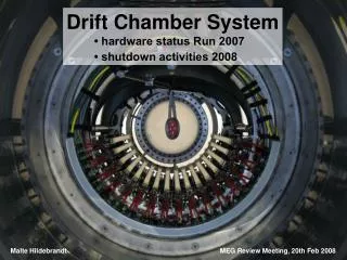
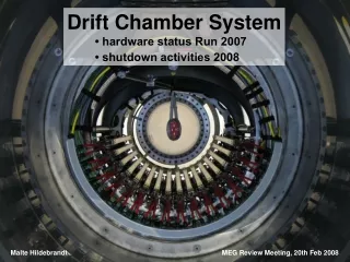
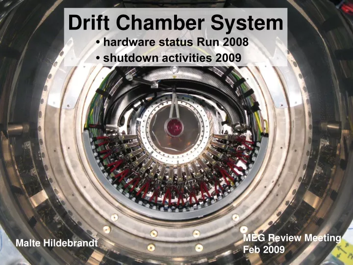
Drift Chamber System • hardware status Run 2008 • shutdown activities 2009. MEG Review Meeting Feb 2009. Malte Hildebrandt. Outline. • installation 2008 • MEG Run 2008: • characteristics of HV instabilities • tests with dc system in MEG

E N D
Drift Chamber System • hardware status Run 2008 • shutdown activities 2009 MEG Review Meeting Feb 2009 Malte Hildebrandt Malte Hildebrandt MEG Review Meeting, 18.02.2009
Outline • installation 2008 • MEG Run 2008: • characteristics of HV instabilities • tests with dc system in MEG • tests in laboratory • Shutdown • preparations, tests • first test results • Summary / Outlook Malte Hildebrandt MEG Review Meeting, 18.02.2009
Installation 2008 • main changes/improvements in 2008 compared to installation in 2007: → topics were already noted in last years DC Status Talk at the Review Meeting as „needs to be done“ / „ will be improved“) • improved strain-relief of LV and signal cables at inside patch panel → no disconnected LV cable 2007: LV dc6u disconnected → 13 missing signal channels 2007: 42 missing connections ↔ crucial step during installation: closing end-cap • more detailed analysis of optical survey of dc system → geometrical alignment includes slope of wires along z-axis 2007: wire at constant x and y, parallel to z-axis (UCI group startet to implement slope) Malte Hildebrandt MEG Review Meeting, 18.02.2009
Installation 2008 • main changes/improvements in 2008 compared to installation in 2007: → topics were already noted in last years DC Status Talk at the Review Meeting as „needs to be done“ / „ will be improved“) • optimised target → new support spacers and 2007: target slightly misaligned new attachment screw-plate to correct position in space → slant angle adjusted to (20.5 ± 0.3)° 2007: (12.8 ± 0.5)° Malte Hildebrandt MEG Review Meeting, 18.02.2009
Target 2008 2007 Malte Hildebrandt MEG Review Meeting, 18.02.2009
Installation 2008 • main changes/improvements in 2008 compared to installation in 2007: → topics were already noted in last years DC Status Talk at the Review Meeting as „needs to be done“ / „ will be improved“) • optimised target → new support spacers and 2007: target slightly misaligned new attachment screw-plate to correct position in space → slant angle adjusted to (20.5 ± 0.3)° 2007: (12.8 ± 0.5)° → identification marks on target Malte Hildebrandt MEG Review Meeting, 18.02.2009
Installation 2008 • main changes/improvements in 2008 compared to installation in 2007: → topics were already noted in last years DC Status Talk at the Review Meeting as „needs to be done“ / „ will be improved“) • optimised target → new support spacers and 2007: target slightly misaligned new attachment screw-plate to correct position in space → slant angle adjusted to (20.5 ± 0.3)° 2007: (12.8 ± 0.5)° → identification marks on target → measurements of inclination: • conventional (sliding rule) 2007(2008): conventional • photogrammetric 2007: photogrammetric • optical survey Malte Hildebrandt MEG Review Meeting, 18.02.2009
New DC HV Modules ↔ S.Ritt ↔ R.Schmidt • during Run 2008: modification of dc HV modules • observation (in 2007, June - July 2008): • several times “blocking” / “freezing” of complete communication: MSCB Submaster, HV nodes, LabView • in combination with HV trips of several HV modules but: cause and effect not clear… → new HV modules: • watchdog: reboot of mController in case of missing toggle signal from mController (→ HV off) • new bus driver: „state machine“ decouples from the bus when not transmitting data → no blocking of bus line with „active high signal“ in case mController stucks • smaller capacitance at HV_output reduces trip propagation within HV module • geographical addressing of nodes within crates Malte Hildebrandt MEG Review Meeting, 18.02.2009
HV Performance • summary: • many dc planes / modules suffered from frequent HV trips • consequently theses planes / modules could only be operated with reduced HV settings → huge impact on overall performance of dc system (→ talk by B.Molzon) Malte Hildebrandt MEG Review Meeting, 18.02.2009
HV Performance • summary: • many dc planes / modules suffered from frequent HV trips • consequently theses planes / modules could only be operated with reduced HV settings → huge impact on overall performance of dc system (→ talk by B.Molzon) • phase 1: June – July • 30 / 32 planes >1800 V(remark: nominal 1850 V) m beam • 2 planes showed problems right from beginning • phase 2: Aug • dc system most of the time off, short period on p beam • 19 / 32 planes >1800 V • 6 / 32 planes 1700-1800 V • phase 3 : Sep – Dec • further deterioration of HV performance m beam • 11 / 32 planes >1800 V • 7 / 32 planes 1700-1800 V Malte Hildebrandt MEG Review Meeting, 18.02.2009
Phase 1 • phase 1: June – July • m beam, start-up phase, e.g. HV ramping • 2 dc planes showed problems right from beginning • dc10A: always <1300-1500 V • dc03A: once 1850 V, then setback down to 1300 V, recovery within weeks up to 1700 V • all other planes: air admixture to COBRA gas (outside module) necessary to achieve stable dc operation → cHelium ≈ 95-96 % (reading O2 sensors) (instead of „pure“ helium level around 99.0-99.5 %) Malte Hildebrandt MEG Review Meeting, 18.02.2009
Air Admixture Sat, 19.07., 02:00 32ccm / 2000ccm (1.60%) cHelium=99% ~96-97 % ~95-96 % ~95-96 % ~94-95 % cHelium=95% cHe= ~93 % Wed, 16.07., 12:40 24ccm / 2000ccm (1.20 %) Mon, 30.06., 08:15 30ccm / 2000ccm (1.5 %) Tue, 01.07., 08:45 55ccm / 2000ccm (2.75 %) Sun, 06.07., 23:00 40ccm / 2000ccm (2.00 %) Sat, 12.07., 15:00 32ccm / 2000ccm (1.60 %) Mon, 30.06., 17:45 65ccm / 2000ccm (3.25 %) Malte Hildebrandt MEG Review Meeting, 18.02.2009
Phase 1 • phase 1: June – July • m beam, start-up phase, e.g. HV ramping • 2 dc planes showed problems right from beginning • dc10A: always <1300-1500 V • dc03A: once 1850 V, then setback down to 1300 V, recovery within weeks up to 1700 V • all other planes: air admixture to COBRA gas (outside module) necessary to achieve stable dc operation → cHelium ≈ 95-96 % (reading O2 sensors) (instead of „pure“ helium level around 99.0-99.5 %) → end of July: 30 / 32 planes operational with >1800V (remark: nominal 1850 V) • occasional problems with communication of HV modules / MSCB / LabView → modify HV modules during XEC run Malte Hildebrandt MEG Review Meeting, 18.02.2009
Phase 2 • phase 2: August • p beam, XEC run, Dalitz run • XEC run: • dc gas system running continuously • dc HV system off for 2½ weeks (modifications of HV modules) • 10 days dc HV at 800-1000 V • Dalitz run (e+ e- identification in Dalitz decay p0 → e+ e-g) • 5 days dc HV on nominal values → current load/plane: 0.7-1.0 mA (compared to 10-12 mA with m beam) • but: many HV trips, number of „weak“ planes increased → beginning of September: • 19 / 32 planes >1800 V • 6 / 32 planes 1700-1800 V Malte Hildebrandt MEG Review Meeting, 18.02.2009
Phase 3 • phase 3: September – December • m beam: MEG physics run • several tests with running system: • to understand reason of HV trips → see separate transparency • to possibly stop or even recover deterioration • but still: many HV trips, number of „weak“ planes increased further → end of December: • 11 / 32 planes >1800 V • 7 / 32 planes 1700-1800 V • in parallel: new test setup in laboratory (HV pcb, potting of capacitors, HV) → see separate transparency Malte Hildebrandt MEG Review Meeting, 18.02.2009
HV Trips • characteristics of HV trips: • individual „treshold effect“ for affected planes • deterioration due to frequent trips (due to damage?) • no obvious correlation with beam off/on, magnetic field off/on or muon target/CW target tube ↔ exception for 2-3 planes: • beginning of run period: HV trip while beam blocker opened → improved during run time („training“ ?) • during run period: HV trip 10-20 min after beam blocker closed Malte Hildebrandt MEG Review Meeting, 18.02.2009
HV Trips • characteristics of HV trips: • beginning of run period: air admixture to COBRA gas necessary to achieve stable dc operation → cHelium ≈ 95-96 % • significant deterioration started after: • p beam time (XEC, Dalitz) • 2-3 months with dc + COBRA gas and HV → at beginning: same planes affected as in 2007 • further deterioration due to frequent HV trips during remaining run time (2008: May – Dec) even without any further p beam time • stable operation (with reduced HV settings) during second p beam time (5 days) 2007: cHelium ≈ 96 % 2007:p at end of run 2007: after 2-3 months with gas and HV 2007: similar, but: shorter run time (Sep – Dec) 2007: dc system off during p beam time Malte Hildebrandt MEG Review Meeting, 18.02.2009
HV Trips • characteristics of HV trips: • beginning of run period: air admixture to COBRA gas necessary to achieve stable dc operation → cHelium ≈ 95-96 % • significant deterioration started after: • p beam time (XEC, Dalitz) • 2-3 months with dc + COBRA gas and HV → at beginning: same planes affected as in 2007 • further deterioration due to frequent HV trips during remaining run time (2008: May – Dec) even without any further p beam time • stable operation (with reduced HV settings) during second p beam time (5 days) 2007: cHelium ≈ 96 % 2007:p at end of run 2007: after 2-3 months with gas and HV 2007: similar, but: shorter run time (Sep – Dec) 2007: dc system off during p beam time → deterioration due to p beam time ? Malte Hildebrandt MEG Review Meeting, 18.02.2009
HV Trips • characteristics of HV trips: • beginning of run period: air admixture to COBRA gas necessary to achieve stable dc operation → cHelium ≈ 95-96 % • significant deterioration started after: • p beam time (XEC, Dalitz) • 2-3 months with dc + COBRA gas and HV → at beginning: same planes affected as in 2007 • further deterioration due to frequent HV trips during remaining run time (2008: May – Dec) even without any further p beam time • stable operation (with reduced HV settings) during second p beam time (5 days) 2007: cHelium ≈ 96 % 2007:p at end of run 2007: after 2-3 months with gas and HV 2007: similar, but: shorter run time (Sep – Dec) 2007: dc system off during p beam time → deterioration due to p beam time ? → deterioration due to helium environment ? Malte Hildebrandt MEG Review Meeting, 18.02.2009
Tests during MEG Run • infrastructure / hardware: • independent Bertan HV power supplies • HV cables • trip test with oscilloscope (MEG and lab) → no improvement • variation of dp_dc regulation value (pdc-pCOBRA): • ↔ small leaks ? Malte Hildebrandt MEG Review Meeting, 18.02.2009
Location of HV Problems • HV problems at top of U-branches: systematics or just by chance? 15th Oct 2008 → due to difference in ρof He and He/C2H6: • dc operation at slightly lower dp_dc level of dp_dc measurement dp • dc operation at slightly higher dp_dc Malte Hildebrandt MEG Review Meeting, 18.02.2009
Location of HV Problems • HV problems at top of U-branches: systematics or just by chance? 15th Oct 2008 → due to difference in ρof He and He/C2H6: • dc operation at slightly lower dp_dc level of dp_dc measurement dp • dc operation at slightly higher dp_dc Malte Hildebrandt MEG Review Meeting, 18.02.2009
Tests during MEG Run • infrastructure / hardware: • independent Bertan HV power supplies • HV cables • trip test with oscilloscope (MEG and lab) → no improvement • variation of dp_dc regulation value (pdc-pCOBRA): • ↔ small leaks ? • 0.2 Pa → 2.0 Pa → -10% current/plane due to breathing of dc modules → no improvement • increase ethane fraction in dc counting gas: • ↔ inside sensitive volume ? • He/C2H6: 50/50 → 45/55 → reduction of gas gain by nearly factor 2 → no improvement Malte Hildebrandt MEG Review Meeting, 18.02.2009
Tests during MEG Run • increase air admixture to COBRA: • ↔ outside dc module • phase 1: cHelium ≈ 95-96% • cHelium ≈ 95-96% → ~40% → 0 % → only test that showed effect → but not that clear result as expected for obvious problem „outside of dc module“ → summary of tests with dc system during MEG run period: • no clear cause and effect • but: hint, that problem is connected to longterm exposure to helium (inside and/or outside of dc module) and - at least in some cases - is located outside of dc module! → ensure helium atmosphere during christmas holidays and shutdown → see separate transparency Malte Hildebrandt MEG Review Meeting, 18.02.2009
Tests in Laboratory • check of common aspects of construction/assemby • sequence of production and assemby → no hint from logbook • wire tension → no hint from logbook • HV pcb • sealing/potting of capacitors • sealing/potting of HV soldering spot 2007: several times weak point → new test setup: • HV test setup • pcb, potting material • helium environment • T ≈ 40-45° C • longterm test (>3 months) Malte Hildebrandt MEG Review Meeting, 18.02.2009
HV Test Setup in Lab → new test setup: • HV test setup • pcb, potting material • helium environment • T ≈ 40-45°C • longterm test (>3 months) Malte Hildebrandt MEG Review Meeting, 18.02.2009
HV Test Setup in Lab • 6 test samples: • 2 samples concentrating on sealing of HV cable, no resistors, no capacitors (Fri, Nov 7th) • 2 samples with HV cable, resistors, capacitors (Fri, Nov 7th, Thu, Nov 13th) • 1 sample with pcb_left and pcb_right (Thu, Nov 13th) • 1 sample: pcb glued on Cu-plate (Thu, Nov 20th) • all tested in air at 2kV • status test: • cHelium > 99% (reading of three O2 sensors) • all HVs at 1990V • T = 40-45°C (since Mon, Nov 24th) → update 17.02.2009: • no significant deterioration (still 2kV) → no conclusion for “aquarium” test (“aquarium” = dc test setup in laboratory during shutdown) Malte Hildebrandt MEG Review Meeting, 18.02.2009
2nd Pressure Control System • construction of 2nd pressure control system for laboratory → operate „aquarium“ independently from MEG pressure control system reminder: • „aquarium“: • setup to operate two dc modules with He/C2H6 as counting gas • within helium atmosphere Malte Hildebrandt MEG Review Meeting, 18.02.2009
Helium Cabin → ensures helium environment for dc system during „waiting time“ in lab → cHelium ≈ 95% (conditions like in COBRA) • closed volume (V = 5.7m3) • windows / frames removable → access to dc modules • operated with the MEG pcs • helium sensor in exhaust line of helium cabin (instead of dc exhaust line) • patch panel is interface/accessible → dc system can be operated like in COBRA Malte Hildebrandt MEG Review Meeting, 18.02.2009
Test Tesults → first results from dc module tests in laboratory • weak point: potting of HV soldering spot on pcb Malte Hildebrandt MEG Review Meeting, 18.02.2009
HV Connection → weak point: potting of HV soldering spot on pcb hood readout hood Vernier pattern anode decoupling capacitors pre-amplifier cards HV connection to pcb + sealing Malte Hildebrandt MEG Review Meeting, 18.02.2009
HV Sealing → nominal condition cable isolation dielectricum potting pcb HV line braided shield → observation after run period several pottings show: • change of shape („flowed away“) • change of color (white → brown) • same observation in 2007/8 (badly applied? no!) Malte Hildebrandt MEG Review Meeting, 18.02.2009
HV Soldering Spot Malte Hildebrandt MEG Review Meeting, 18.02.2009
Test Tesults → first results from dc module tests in laboratory • weak point: potting of HV soldering spot on pcb → replace ThreeBond 1530 with epoxy EPO-TEK 302-3M Malte Hildebrandt MEG Review Meeting, 18.02.2009
Test Tesults → first results from dc module tests in laboratory • weak point: potting of HV soldering spot on pcb → replace ThreeBond 1530 with epoxy EPO-TEK 302-3M • „circumstantial evidence lawsuit“ (no glow by eye, IR camera, ...): • signals on oscilloscope: positive anode signals negative cathode signals • change of gas mixture: no effect (or long delay) → discharge between anode channel and GND but: not towards cathode strip and not in sensitive volume maybe towards frame at the edge or on pcb itself → open dc module to verify or falsify: • wires and cathode foil fine • edges of isolators fine → closer look at vias on pcb Malte Hildebrandt MEG Review Meeting, 18.02.2009
HV Via top layer GND +HV bottom layer 7 mm Malte Hildebrandt MEG Review Meeting, 18.02.2009
dc01A glue no glue no glue Malte Hildebrandt MEG Review Meeting, 18.02.2009
He / C2H6 He air glue glue glue G10 isolator glue G10 isolator glue carbon frame PCB Cross Section bottom layer top layer pcb pcb bottom layer +HV +HV GND Malte Hildebrandt MEG Review Meeting, 18.02.2009
PCB Cross Section d pcb pcb +HV +HV GND glue glue glue G10 isolator glue G10 isolator glue carbon frame Malte Hildebrandt MEG Review Meeting, 18.02.2009
PCB Cross Section d pcb pcb +HV +HV GND glue glue glue G10 isolator glue G10 isolator glue carbon frame Malte Hildebrandt MEG Review Meeting, 18.02.2009
PCB Cross Section d pcb pcb +HV +HV GND glue glue glue G10 isolator glue G10 isolator glue carbon frame Malte Hildebrandt MEG Review Meeting, 18.02.2009
PCB Cross Section pcb pcb +HV +HV GND glue glue glue G10 isolator glue G10 isolator glue carbon frame Malte Hildebrandt MEG Review Meeting, 18.02.2009
Depth of HV Vias dc01A → example: depth of HV via on dc01A upstream downstream a0 0.73 ± 0.03 0.76 a1 0.47 0.80 a2 0.39 0.66 a3 0.14 0.83 a4 0.65 0.67 a5 0.57 0.46 a6 0.64 0.61 a7 0.00 0.47 a8 0.57 0.57 ddesign = 0.80 ± 0.02 location of discharge (identified by signals) remark: all numbers in mm Malte Hildebrandt MEG Review Meeting, 18.02.2009
PCB Cross Section He / C2H6 pcb pcb +HV +HV GND glue glue G10 isolator glue G10 isolator glue carbon frame Malte Hildebrandt MEG Review Meeting, 18.02.2009
Next Steps → following activities will start immediately and run in parallel: motto:confirm„viahypothesis“,startnewconstruction/repairworktoproofsolution • operate „dc skeleton“ (2 anodes + middle cathode) in „aquarium“ → no hood cathode: observe discharge ? • prepare new sample for HV test box: • no glue on ring of via • glue only on ring of via • fill via completely with glue → confirm effect of different „via/glue conditions“ • start construction of anode frames with new pcb design Malte Hildebrandt MEG Review Meeting, 18.02.2009
HV Print 2009 pads for resistors HV print 2009 • traces for HV on middle layer → no HV traces on bottom layer → individual layers with „only HV“ or „only GND“ (3-layer → 4-layer pcb) • „blind vias“ → vias have only necessary depth to connect appropiate layers (like „blind hole“) print 2007 outer edge inner edge +HV traces vias for +HV GND print 2009 Malte Hildebrandt MEG Review Meeting, 18.02.2009
Next Steps → following activities will start immediately and run in parallel: motto:confirm„viahypothesis“,startnewconstruction/repairworktoproofsolution • operate „dc skeleton“ (2 anodes + middle cathode) in „aquarium“ → no hood cathode: observe discharge ? • prepare new sample for HV test box: • no glue on ring of via • glue only on ring of via • fill via completely with glue → confirm effect of different „via/glue conditions“ • start construction of anode frames with new pcb design → operate 1st and 2nd dc in „aquarium“ to confirm long term behaviour → chance to check for additional „hidden“ weak point (masked by „via problem“) Malte Hildebrandt MEG Review Meeting, 18.02.2009
Time Schedule → following activities will start immediately and run in parallel: motto:confirm„viahypothesis“,startnewconstruction/repairworktoproofsolution detector laboratory February – March • „dc skeleton“ in aquarium • „via test“ with pcb • test new dc‘s in aquarium April – July • ongoing test in aquarium July – August • test of dc system in support structur in laboratory beginning of September → dc system ready for installation in MEG experiment detector workshop • construction of new dc‘s: anodes with new pcb recycled cathode + hood • ongoing construction Malte Hildebrandt MEG Review Meeting, 18.02.2009
New DC Preamplifier • goal: • improve signal/noise ratio → improve R- and z-resolution for small signals → improve efficiency • argument: • analysis of experimental data 2007 using low-pass digital filter: → improvement in z-resolution and 10% higher efficiency • solution: • select low-noise operational amplifier • adapt schematics → bandwidth reduced from 140MHz to 80MHz • status: • few prototypes produced and tested → signal/noise ration improved by factor 1.5 • to do: • direct comparison of old and new preamplifier with real signals → dc in „aquarium“ with cosmics and 90Sr Malte Hildebrandt MEG Review Meeting, 18.02.2009
Summary / Outlook • many dc planes / modules suffered from frequent HV trips • consequently theses planes / modules could only be operated with reduced HV settings → huge impact on overall performance of dc system and MEG experiment • many tests were performed in MEG experiment and in laboratory in order to understand this problem including: upgrade and construction of new laboratory infrastructure • following weak points were identified so far: • potting of HV soldering spot on pcb → seal with epoxy • HV via on pcb → anode frames with new pcb design • ongoing activities: • confirm via hypothesis • start construction/repair work to proof solution → dc system ready for installation at beginning of September Malte Hildebrandt MEG Review Meeting, 18.02.2009