Download
1 / 22
230 likes | 438 Views
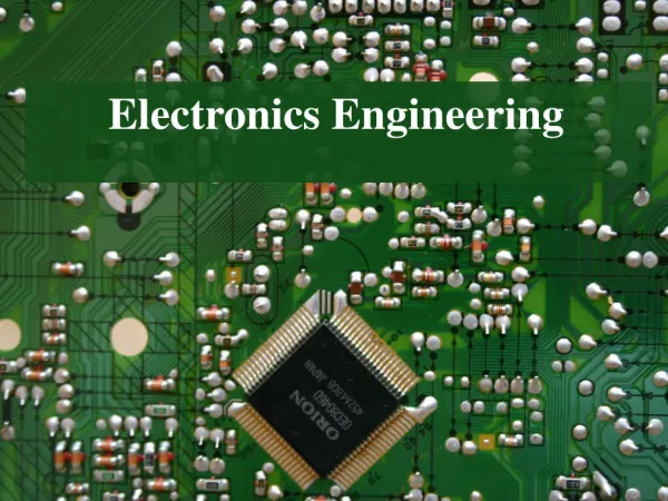
ELECTRONICS ENGINEERING. Before we start with Electronics Let us review the Basics of Electricity. Q. What are the two main quantities in electricity ?. CURRENT. VOLTAGE. What is Current?. What is Voltage?. What is a Voltage Source ?. A device that produces voltage output continuously.

E N D
Before we start with Electronics Let us review the Basics of Electricity Q. What are the two main quantities in electricity ? • CURRENT • VOLTAGE
What is a Voltage Source ? • A device that produces voltage output continuously. TYPES:- • DC Voltage Source and AC Voltage Source
What is a Current Source ? • A voltage source that has a very high internal impedance as compared with external load impedance is a Constant Current Source. • Example: A dc battery of 1000 V with internal resistance 950kΩ and load resistance varying from 50 KΩ to 150 KΩ.
Series and Parallel Connections • Two 12 V batteries in series • Two 12 V batteries in parallel • What will be the output voltage if a 24 V battery is connected in parallel with a 12 V battery?
Applications:- • Rectification • Amplification • Control • Generation • Conversion of Light into Current • Conversion of Current into Light The branch of engineering which deals with current conduction through a vacuum, or gas or semiconductor is known as electronics.
Classification of Solids Conductors, Insulators and Semiconductors • Insulators: (e.g. wood, glass) • Conductors: (e.g. copper, aluminum) • Semiconductors: (e.g. germanium, silcon)
Semiconductors • A semiconductor is a substance which has conductivity (2 to 2000/ ohm-meter) in between conductors and insulators e.g. germanium, silicon, carbon etc. • A semiconductor is a substance which has almost filled valence band and nearly empty conduction band with a very small forbidden energy gap i.e. 1.1eV for silicon and 0.7eV for germanium.
Intrinsic & Extrinsic semiconductors • A semiconductor in an extremely pure form is known as an intrinsic semiconductor. • The intrinsic semiconductor has little current conduction capability at room temperature. • To be used in electronic devices, the conducting properties of intrinsic semiconductor are significantly increased by adding a small amount of suitable impurity, it is then called extrinsic semiconductor. • The process of adding impurities to a pure semiconductor is known as doping. Man adding water to milk
P-N Junction • If a semiconductor is doped with p-type impurities at one end and n-type impurities at the other end, a p-n Junction is formed
Diode • It is a one way valve. • It allows current to flow in one direction only. • It is commonly used (as a switch) in making Power supply to convert ac voltage into dc voltage.
Half-wave rectifier – A diode placed in series between a transformer (or ac line input) and its load. Half-wave Rectifiers
This circuit converts an ac input to a series of positive pulses. Positive Half-wave Rectifiers
Negative Half-wave Rectifiers This circuit converts an ac input to a series of negative pulses.
The negative full-wave rectifier converts an ac input to a series of negative pulses. Negative Full-wave Rectifiers
The most commonly used because: It does not require the use of a center-tapped transformer. It can be coupled directly to the ac power line. It produces a higher dc output than a comparable full-wave center-tapped rectifier. Full-Wave Bridge Rectifiers
Digital Circuits • Digital circuits are prepared using analog components like transistor as a switch. • The binary numbers 1 and 0 are represented by +5Volts and 0Volts.