Download
1 / 22
260 likes | 733 Views
Radar Remote Sensing. RADAR => RA dio D etection A nd R anging. Radar Remote Sensing. Active remote sensing system using 1 cm to 1m wavelengths (microwaves). Microwave Atmospheric Window. Radar Systems. AIRSAR - Flies in DC-8 with C, L, and P bands

E N D
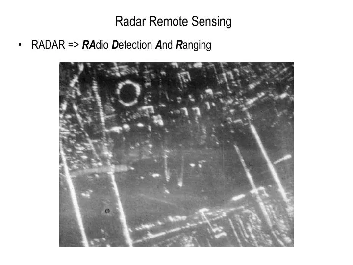
Radar Remote Sensing • RADAR => RAdio Detection And Ranging
Radar Remote Sensing • Active remote sensing system using 1 cm to 1m wavelengths (microwaves).
Radar Systems • AIRSAR - Flies in DC-8 with C, L, and P bands • SRTM (Shuttle Radar Topography Mission) • - X-band and C-band radar
Radar Applications • Radar imaging • Measure returned energy flux • Return controlled by dielectric constant (index of refraction) of materials, roughness of surface at wavelength scale, and slopes • Radar altimetry • Measure round trip travel time to determine distance between antenna and surface • Radar interferometry • Broadcast from one antenna and receive at two antenna with known distance between them • Phase difference for two antennas used to determine topography.
Characteristics of Radar Images • SLAR - Side-Looking Airborne Radar • SAR - Synthetic Aperture Radar (also side-looking) • Side-looking characteristics induce some geometric effects quite distinct from framing cameras.
Characteristics of Radar Images • Radar records strength of returned signal and round trip travel time to determine pixel brightness and location of pixel perpendicular to flight direction, respectively.
Radar Remote Sensing • Radar Image Characteristics • Shadows • Foreshortening • Layover • Relief Displacement • Radar Spatial Resolution • Cross Track or Range Resolution • Along Track Resolution • SLAR • SAR
Radar Image Characteristics • For side-looking radar systems, position within an image line is determined by travel time of radar beam. • Multiple image lines are created by forward motion of aircraft or satellite.
Radar Shadows • Radar shadows occur when slopes are not seen by radar beam. That is, when slope angle is greater than the depression angle. • Shadow lengths get longer behind obstacles as depression angle gets smaller.
Radar Shadows • For simple terrain (flat with bumps), shadows can be used to get heights. • See diagram below. H = aircraft altitude, h = feature height,Rr = slant range to far end of shadow, Rs = slant range length of shadow. • Distances measured on slant range image.
Foreshortening • Given that range determines cross-track pixel location, there is geometric foreshortening. • Cross-track length of feature determines how long it remains in radar illumination. • If surface slope is normal to wave front, then slope appears as a point in output image. • Foreshortening is one reasonwhy radar is side-looking.Features directly beneathaircraft would have same return times andthus show as single point.
Foreshortening Example • Seasat image of Alaska. Radar illumination is from the top.
Foreshortening • Surfaces seen with largest depression angles (closest to antenna) will have greatest amount of foreshortening. • Foreshortening decreases as the depression angle decreases (i.e., further from antenna) for a given surface slope. • Example of foreshortening for slopes of 15º from horizontal.
Layover in Radar Images • Layover occurs when slopes are steep that for return from top of slope is received before the return from the bottom of slope. • Object appears to be "laying over" on its side in the radar image. • Layover increases as depression angle increases.
Layover Example • Seasat image of Alaska. Radar illumination is from the top.
Layover Example • Mount Fujiyama, Japan. Radar illumination from the top.
Radar Image Spatial Resolution • Separate values of resolution for the along-track and cross-track directions. • Consider cross-track or range resolution. • Range resolution dependent on pulse length, t, and on depression angle, b. Not dependent on antenna altitude. • Two features will be resolved in the range direction if their return pulses do not arrive back at the antenna at the same time.
Range Resolution • Pulse length in distance is t*c. • Assume that features are separated inrange direction if horizontal separation(Rr),is greater than (t*c)/2. • From the triangle in diagram, we canderive range resolution (Rr). • As pulse length and depression angledecrease, the range resolution gets smaller.Better resolution further from the antenna. • As depression angle increase for points closerto the antenna, range resolution is worse. • Another reason why radar can not image directlybeneath the antenna.
Along-Track Resolution • Along-track resolution in independent of the range resolution. • For simple SLAR system, the along-track cell size (Ra)is dependent on beam width projected onto the ground. Beam width and thus along-track resolution becomes wider for distances further from the antenna. • Where S is slant range, l is radarwavelength, and D is antenna width. • Equation is derived from fact that beamwidth is proportional to l/D. • For SAR systems, a longer antennais synthesized for greater slant rangesto maintain a constant along-trackresolution.