Download
1 / 30
330 likes | 712 Views
Antenna Design Tools VE3KL. Antenna simulation tools based on NEC Fortran Program Eznec 4NEC2 (free) including optimizer and tuner design Transmission Line Utility (TLDetails, Dan Maguire, AC6LA ) Antenna Tuner Utility (included in 4NEC2)

E N D
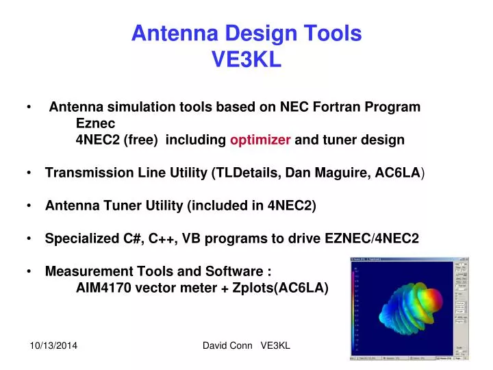
Antenna Design ToolsVE3KL • Antenna simulation tools based on NEC Fortran Program Eznec 4NEC2 (free) including optimizer and tuner design • Transmission Line Utility (TLDetails, Dan Maguire, AC6LA) • Antenna Tuner Utility (included in 4NEC2) • Specialized C#, C++, VB programs to drive EZNEC/4NEC2 • Measurement Tools and Software : AIM4170 vector meter + Zplots(AC6LA) David Conn VE3KL
Outline • My Antenna Design Process • 4nec2 Overview..Analysis, Optimization, Utilities • Design Example …..40/17 metre fan dipole • Future Trends • Demo of 4NEC2 or AIM4170 Analyzer David Conn VE3KL
Antenna System Simulate/build/test Antenna Transmission Line Zo, velocity, length losses Use TLDetails to select Tuner Discrete or Stubs Optional : use if SWR >1.5 Transmitter Power and Frequency David Conn VE3KL
My Design Process Build Measure Vector Z meter Aim 4170 ….. Idea ? 4nec2 Simulator Optimizer File Transfer .csv Capture Data for plotting Zplots Software Transmission Line Analysis (TLDetails) Design Review OK ? Start Over? Tuner Design 4NEC2 Matching Utility David Conn VE3KL
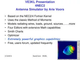
4nec2 ArieVoors • A free full featured antenna simulator • Uses the nec FORTRAN kernel • Several input editors • Built-in 3D graphics • Excellent help file • Many standard antennas….helix etc. • First free simulator to contain an optimizer David Conn VE3KL
Spherical Coordinate System Z θ Rx Antenna Elevation angle = 90 - θ Tx Antenna Y XY Horizontal Plane Z Vertical axis φ X φ is the horizontal azimuth angle Θ is the angle measured from vertical David Conn VE3KL
Method of Moments • A discrete numerical method • Divide wires into many segments • 25 segments per wavelength David Conn VE3KL
4nec2 Simulation Use built-in editor to the Define Antenna Geometry Analyze Gain,SWR… Optimize (Tune) Use Matching Utility to Design Tuner if Needed Use TL Details to select Transmission line David Conn VE3KL 8
The Big Gun (Optimization)Optimize (Tune) a 2 metre dipoleto 6 metres Adjust reactance to zero Vary Length Results L= 2.8 metres Xin = -0.13 Ohms David Conn VE3KL
4NEC2 Far Field Traditional Plot • Several Views • Vertical, Horizontal, Total • Circular Polarization • RHC, LHC, Total David Conn VE3KL
3D VE3XK 50 MHz Stack 50 MHz OMNI Source Side Along X Axis Right Hand Circular Polarization Shown All Graphs are dynamic David Conn VE3KL
4NEC2 3D Near Field David Conn VE3KL
4NEC2 Advanced Far Field Map θ High Gain φ David Conn VE3KL
Spherical Coordinate System Z θ Rx Antenna Elevation angle = 90 - θ Tx Antenna Y XY Horizontal Plane Z Vertical axis φ X φ is the horizontal azimuth angle Θ is the angle measured from vertical 10/13/2014 David Conn VE3KL 14
Examples “Simple” 2m Dipole Free Space -L/2 L/2 X Axis Total Gain Theta = 75 degrees PHI = 311 degrees David Conn VE3KL
Simple 2m Dipole .. Horizontal Plane -L/2 L/2 X Axis Horizontal Plane BLUE :Vertical E Field RED: Horizontal E Field Green: Total Field Theta = 45 degrees (Is it OK to say that a dipole is Horizontally Polarized? No!) Receives Power Line Noise off the end (Vertically Polarized) David Conn VE3KL
4NEC2 Several Views of Frequency Response David Conn VE3KL
4NEC2Smith Chart David Conn VE3KL
A Design ExampleTwo Element Fan Dipole40/17 metres Wire Lengths? Tuner needed? Frequency Response? Gain and direction of radiation? Mounted between two towers (North South) Simulate/Build/Test 10/13/2014 David Conn VE3KL 19
Two Element Fan DipoleFour Wires Connected to a Transmission Line L1 (1/4 Lambda) 40 metre top section 30 degrees 17 metre bottom section (Inverted V) L2 (1/4 Lambda) Height RG8-X Cable (Length, Losses, Zin) Tuner Transmitter Lossy Ground 10/13/2014 David Conn VE3KL 20
Two Element Fan Dipole40 Metre Gain Pattern……broadside radiation 10/13/2014 David Conn VE3KL 21
Two Element Fan Dipole17 Metre Gain Pattern……45 degree lobes 10/13/2014 David Conn VE3KL 22
Two Element Fan DipoleFrequency Response ..SWR around 1.5Tuner might be useful Very High SWR ??? Good Candidate for an auto-tuner David Conn VE3KL 23
Two Element Fan DipoleFrequency Response…… ImpedanceZ= 28.5+j2 Ohms @ 18 MHz 10/13/2014 David Conn VE3KL 24
TLDetails to select the Transmission LineLength needed = 15 Metres Zin = 40 + j 20 David Conn VE3KL
Matching (4nec2 Utility)18 MHz No need for Xs David Conn VE3KL
Measurements Antenna or other DUT Aim 4170 Vector Z Meter Complete Data Set Generated Import Data to Zplots or Excel or Data Base (SQLITE) Plotting or Further Computing E.g.. Calculate Cable Losses .csv AIM 4170 Vector Impedance Meter Connected to Computer via Serial Port 27
Fan DipoleMeasurements AIM4170 & Zplots Measured Simulated David Conn VE3KL 28
The Future • Much more software integration needed • link measurement tools to all software • include data base output for all software • use Excel and SQLite data bases • standard data base file format • Models, especially ground types need improvement • Much more work on optimization • Electrical design to mechanical drawing needed for Microwave Antennas • 2010 Antenna design tools similar to Silicon IC design in its infancy
Summary • Antenna/Simulation Tools are well developed • See VE3KL’s articles in TCA for more details • Presentation posted on ve3kl.com Web Site VY 73 Dave VE3KL