Download
1 / 44
440 likes | 563 Views
Lecture 5 – Data M o deling . BCIS 4610. Today’s Agenda. Schedule, updates Requirements for Interim report Data modeling Using Oracle Designer. Schedule. Announcements. Grades posted on the Web by a PIN number HW 2 due Oct 1 Ch. 7, Pr 11 from your book

E N D
Lecture 5 – Data Modeling BCIS 4610
Today’s Agenda • Schedule, updates • Requirements for Interim report • Data modeling • Using Oracle Designer BCIS 4610, Fall 2008
Announcements • Grades posted on the Web by a PIN number • HW 2 • due Oct 1 • Ch. 7, Pr 11 from your book • To be completed in Oracle Designer • Tutoring hours tomorrow Th. reduced to 8-10 PM • Proposals feedback – at the end of the class – may need rework for some teams • Start working towards the interim report – due Oct 15 BCIS 4610, Fall 2008
Interim report • Title page and table of contents • Executive summary • Discussion of the problem – from the proposal • Description of system requirements with references to the appendix • Discussion of requirements collection • Description of the process to be supported by the system (ref to DFDs and Process maps) • Description of data to be processed and used by the system (ref to ERDs, CRUD) • Description of user interface requirements • Other requirements • Verbal discussion of the proposed system with references to the appendix • Definition of work for Stage 2 (forms, reports, plan) • Appendix • Level 0 and Level 1 DFDs • Business Process Maps • ERD • Crud Matrix • Functional Hierarchy Diagram • Entity Model Reference Report • Function Definition Report • Dataflow and data store definition reports BCIS 4610, Fall 2008
System Requirements Determination BCIS 5120, Spring 2008
Data models • Data models may also be referred to as static models. • They describe the kinds of things that exist within the scope of the solution, the information that the system records about those things, the way that they relate to one another, and the rules that govern their behavior. • The data model does not show how the solution behaves through time, or how persons outside the solution scope interact with the solution.
Data modeling techniques • Entity-relationship diagrams • Data dictionaries • CRUD matrix • Other: • Class Diagrams BCIS 4610, Fall 2008
Entity Relationship Diagrams • An Entity Relationship Diagram (ERD) is a visual representation of a data structure. • ERDs describe things that are significant to the enterprise (e.g. Customers, Products, Employees, Invoices, etc.) and are useful in describing the structure of the business itself, and many of the rules by which it is governed. • An Entity Relationship Diagram is a visual representation of : • the entities of interest to the solution, • the information that must be retained about each entity, and • the relationship between them. BCIS 4610, Fall 2008
ERD in Oracle BCIS 4610, Fall 2008
Introduction to Entity-Relationship (E-R) Modeling • Entity-Relationship (E-R) Diagram • A detailed, logical representation of the entities, associations and data elements for an organization or business • Notation uses three main constructs • Data entities • Relationships • Attributes BCIS 5120, Spring 2008
Components of an ERD Entity - person, place, object, event or concept about which data is to be maintained Entity type: collection of entities with common characteristics Entity instance: single entity Relationship - association between the instances of one or more entity types Attribute - named property or characteristic of an entity BCIS 5120, Spring 2008
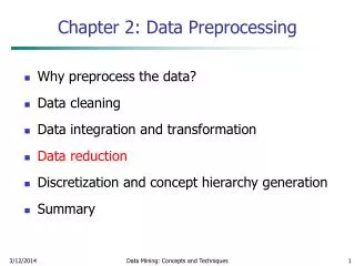
Entity and Attribute Example Simple attributes Identifier attribute… each employee has a unique ID. BCIS 5120, Spring 2008
Relationships: degree and cardinality BCIS 5120, Spring 2008
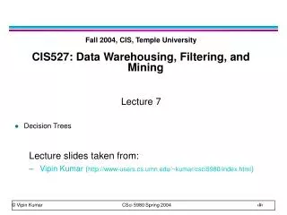
Cardinality Symbols BCIS 5120, Spring 2008
Oracle Cardinality Notations BCIS 4610, Fall 2008
Problem Description Draw as complete an ERD as you can. You must show all cardinalities (low and high) and name the relationship. • 1.A company has many employees. We store each employee's name, SSN, address, salary, sex, and birth date. • 2. The company is organized into departments. Each department has a unique name, a unique number, and a particular employee who manages the department. The department may have several locations. • 3. An employee is assigned to one department, and we keep track of the employee assignments. We also keep track of the direct supervisor of each employee. • 4.Also, we want to keep track of the dependents of each employee for insurance purposes. We keep each dependent's ID, name, sex, birth date, and relationship to the employee. BCIS 5120, Spring 2008
Let’s identify all entitles and their attributes … • 1. EMPLOYEE: name, SSN, address, salary, sex, and birth date • 2. DEPARTMENT: unique name, a unique number, a location and manager (?) • 3. DEPENDENT: name, sex, birth date, and relationship to the employee BCIS 5120, Spring 2008
Address Name Sex Name ID Salary SSN EMPLOYEE DEPENDENT DOB Sex Relationship DEPARTMENT Number Name Location Let’s draw the entitles and their attributes … DOB BCIS 5120, Spring 2008
DOB Address Name Sex ID Name Salary SSN EMPLOYEE DEPENDENT Sex Relationship DEPARTMENT Number Name Location Let’s identify and draw the relationships … DOB BCIS 5120, Spring 2008
DOB Address Name Sex ID Name Salary SSN Has EMPLOYEE DEPENDENT Sex Relationship DEPARTMENT Number Name Location 1. An employee may have min. zero, max. many dependents. Each dependent has to belong to exactly one (min. one, max. one) employee. DOB BCIS 5120, Spring 2008
DOB Address Name Sex ID Name Salary SSN Has EMPLOYEE DEPENDENT Sex Relationship Works DEPARTMENT Number Name Location 2. Each department has min. 1, max. many employees. Each employee works for exactly one (min. one, max. one) department. DOB BCIS 5120, Spring 2008
DOB Address Name Sex ID Name Salary SSN Has EMPLOYEE DEPENDENT Sex Relationship Manag Works DEPARTMENT Number Name Location 3. Each department has exactly one manager. Each employee managers min. zero, max. one department. DOB BCIS 5120, Spring 2008
DOB Address Name Sex ID Name Salary SSN Has EMPLOYEE DEPENDENT Sex Relationship Manag Works Superv. DEPARTMENT Number Name Location 4. Each employee is supervised by exactly one other employee. An employee may be a supervisor for min. zero, max. many other employees. ATTENTION: This is a unary relationship! It is a relationship between instances of EMPLOYEE entity type! DOB BCIS 5120, Spring 2008
Supertypes and Subtypes • Subtype:A subgrouping of the entities in an entity type which has attributes that are distinct from those in other subgroupings • Supertype:An generic entity type that has a relationship with one or more subtypes • Inheritance: • Subtype entities inherit values of all attributes of the supertype • An instance of a subtype is also an instance of the supertype BCIS 5120, Spring 2008
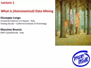
Employee supertype with three subtypes All employee subtypes will have emp nbr, name, address, and date-hired Each employee subtype will also have its own attributes BCIS 5120, Spring 2008
Relationships and Subtypes • Relationships at the supertype level indicate that all subtypes will participate in the relationship • The instances of a subtype may participate in a relationship unique to that subtype. In this situation, the relationship is shown at the subtype level BCIS 5120, Spring 2008
Supertype/subtype relationships in a hospital Both outpatients and resident patients are cared for by a responsible physician Only resident patients are assigned to a bed BCIS 5120, Spring 2008
Constraints in Supertype/ Completeness Constraint • Completeness Constraints: Whether an instance of a supertypemust also be a member of at least one subtype • Total Specialization Rule: Yes (double line) • Partial Specialization Rule: No (single line) • Disjointness Constraints: Whether an instance of a supertype may simultaneously be a member of two (or more) subtypes. • Disjoint Rule: An instance of the supertype can be only ONE of the subtypes • Overlap Rule: An instance of the supertype could be more than one of the subtypes BCIS 5120, Spring 2008
Oracle Notation for Subtype/Supertype BCIS 4610, Fall 2008
Data Dictionary • A data dictionary defines the data that is recorded or used by an organization, including both the primitive data elements and the more complex data structures that will be built out of them. • The data dictionary is typically aimed at non-technical stakeholders in a solution, such as managers and end-users. • Technical stakeholders will generally require that the Data Dictionary be elaborated into a Class Model or Entity-Relationship Diagram. • The Data Dictionary is collected throughout the Requirements Elicitation process by collecting definitions of data used by stakeholders. • When contradictory definitions are encountered or aliases for the same data elements are found to be in use, the Business Analyst must work with stakeholders to reach an agreed definition. BCIS 4610, Fall 2008
Data Dictionary • The following information must be recorded about each data element in the data dictionary: • Name: a unique name for the data element, which will be referenced by the composite data elements. • Aliases: alternate names for the data element used by various stakeholders. • Values/Meanings: a list of acceptable values for the data element. This may be expressed as an enumerated list or as a description of allowed formats for the data (including information such as the number of characters). If the values are abbreviated this will include an explanation of the meaning. • Description: the definition of the data element in the context of the solution. BCIS 4610, Fall 2008
CRUD Matrix • The CRUD Matrix is used to define different levels of access rights to data stored within a software solution. • The CRUD (Create, Read, Update, Delete) Matrix cross-references user groups against the entities managed within a system. For each data element, it states which user groups are allowed to create, read, update, delete, or list those entities. • The CRUD Matrix also requires that a detailed data model be defined for the system, generally through an Entity-Relationship Diagram or a Class Model (covered in BCIS 4640). BCIS 5120, Spring 2008
LEVELS OF ACCESS IN CRUD MATRIX • Create: members of the user group may instantiate new instances of that data element. • Read: members of the user group may view all data stored in the data element. • Update: members of the user croup may change the data stored in the element. • Delete: members of the user group may delete instances of the data element. • List: members of the user group may list all instances of the data element but do not have access to internal data. This is optional and often subsumed into Read. BCIS 5120, Spring 2008
CRUD MATRIX EXAMPLE BCIS 5120, Spring 2008