Download
1 / 22
230 likes | 389 Views
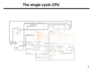
Single-cycle mixed-fluid LNG (PRICO) process. Part I: Optimal design Sigurd Skogestad & Jørgen Bauck Jensen Quatar, January 2009. Single-cycle mixed fluid LNG (PRICO) process. 45 kg/s 30 °C 40 bar. Natural gas : 45 kg/s (1.3 MTPA) Feed at 40 bar and 30 °C

E N D
Single-cycle mixed-fluid LNG (PRICO) process Part I: Optimal design Sigurd Skogestad & Jørgen Bauck Jensen Quatar, January 2009
Single-cycle mixed fluid LNG (PRICO) process 45 kg/s 30 °C 40 bar Natural gas: • 45 kg/s (1.3 MTPA) • Feed at 40 bar and 30 °C • 89.7 mol% C1, 5.5% C2, 1.8% C3, 0.1% C4, 2.8% N2 • Cooled to ~ -156 °C • Expansion to ~ 1 bar • Flash gas may be used as fuel • Liquefied natural gas (LNG) product at -162C -156 °C 35 bar 1 bar -162 °C
Single-cycle mixed fluid LNG (PRICO) process 22 bar Refrigerant: • Mixed fluid: ~ 33mol% C1, 35% C2, 25% C4, 7% N2 • Partly condensed with sea water to ~ 30 °C • Cooled to ~ -156 °C • Expansion to ~ 4 bar • Evaporates in NG HX • Super-heated ~ 10 °C • Compressed to ~ 22 bar 45 kg/s 30 °C 40 bar 475 kg/s 30 °C 22 bar 4 bar Sup 10 °C -156°C 19 bar -156 °C
Design constraints Compressor: • Max. pressure: 22 bar / 30 bar • Max. compressor suction volume*: 317000 m3/h • Max. compressor head*: 263.6 kJ/kg Or: Max. compressor ratio* Pr, e.g. 5.5 (Price) 4. Max. compressor work: 77.5 MW / 120 MW 5. Minimum superheating: 10C 30 °C 40 bar 30 °C 1 bar * Design constraint only -162 °C 3.33 kg/s
min JTAC = Joperation + Jcapital subject to c ≤ 0 Joperation [$/year] is the annual operating cost Joperation = Jutility + Jfeeds + Jproducts Jcapital [$/year] is the annualized cost of the equipment Optimal design: TAC Maximize total profit = Minimize Total Annualized Cost (TAC): • Total annualized cost (TAC) is minimized with respect to the design variables • Flowsheet structure • Areas, sizes • Operating parameters (pressures etc.) • Requires mixed integer non-linear programming • Our case Fixed structure Try a simpler approach
Simpler approach: Specify ΔTmin Idea: Specify ΔTmin to balance between • operating costs (favoured by a low value) • capital costs (favoured by a high value) 30 °C 40 bar 30 °C ΔTmin=2C* 1 bar * Design constraint only -162 °C 3.33 kg/s
Simple ΔTmin-method (Approach 1) • ΔTmin (=2C) is added as an extra design constraint + minimize compressor work (Ws) • BUT: The resulting design parameters (pressure etc.) are not optimal for the resulting process! • Reoptimizing reduces ΔTmin to about 1C and reduces work by about 5% (!) • Cannot be fixed by iterating on ΔTmin • Therefore:Approach 1NOT USED
Simplified TAC (sTAC) Capital cost Jcapital = Σi (Cfixed,i + Cvariable,i·Sini) / T T – capital depriciation time, e.g. 10 years • Structure of plant given Cfixed,i = 0 • Main equipment: Heat exchangers and compressor • Scaling exponent • n = 1 for compressor (Can then combine operation and capital cost!) • n = 0.65 for heat exchangers • Cvariable,i = C0for all heat exchangers Approach 2: Adjust C0 to get ΔTmin = 2C
sTAC – Optimization problem • Minimize cost Case I: Feedrate (NG) given Case II: Feedrate free Here: Consider Case II. Minimize cost= ”Max. single-train LNG feed” 30 °C 40 bar 30 °C 1 bar 3.33 kg/s -162 °C
Resulting “Max feed” sTAC: • Minimization with respect to design parameters (AHOT and ANG) and operating parameters (pressures etc.) • ANG: NG / cold refrigerant • AHOT: hot refrigerant / cold refrigerant • Here: Adjust C0 to obtain ΔTmin = 2C • Other constraints c: depend on specific case
Case 1 – Price and Mortko (1983) • Data • LNG outlet temperature (before expansion) = -144 °C • 77.5 MW compressor power • Maximum Ph = 22 bar • Maximum Pr = Ph/Pl = 5.5 • Differences / uncertainties • Pure methane • Neglected removal of heavy components • Pressure losses (especially important at low pressure, e.g. compressor suction) • Heating of fuel gas produces some LNG “for free” • 3.7 % higher production compared with Price & Mortko • 44.6 kg/s LNG production • Gives large amount of fuel gas (7.7 kg/s, ~230 MW) • Want to limit fuel to 3.33 kg/s, ~100 MW
Case 2 – Limited fuel flow • Limitation on fuel flow instead of outlet temperature • Maximum 3.33 kg/s of fuel (7.7. kg/s in Case 1) • Outlet temperature down from -144 °C to -156 °C to get sufficient cooling with less flash gas (fuel) • Production (with Ws=77.5 MW and Pr=5.5) reduced by 6 % compared with case 1 • From 44.6 kg/s to 41.7 kg/s 22 bar 45 kg/s 30C 475 kg/s 30C 77.5 MW 4 bar -156C -162C 41.7 kg/s 3.33 kg/s
Case 3,4 – Super-heating • Wish to find the optimal degree of super-heating • 10.0 °C super-heating used for all cases except 3 and 4 • Case 3; 11.6 °C super-heating increases production by 0.8 % compared with case 2 • Case 4; 25.7 °C super-heating decreases production by 1.3 % compared with case 3 • Optimum is very flat in terms of super-heating • Some super-heating is necessary to protect the compressor • Some super-heating is optimal due to • Internal heat exchange in the main heat exchanger • However, the heat transfer coefficient in the super-heating region is lower than in the evaporating region • This has not been considered here • Will tend to reduce the optimal amount of super-heating
Case 5 – No pressure constraint • We have removed the following constraints • Maximum Ph = 22 bar • Maximum Pr = Ph/Pl = 5.5 • Ph is increased to 50.4 bar and Pr is increased to 22 • LNG production is increased by 11 % (from case 2) • The high pressure ratio is not possible with a single compressor casing • The compressor head is too high • Two compressors in series will do the job • Higher head [kJ/kg] gives lower refrigerant flow • Cooling duty per kg of refrigerant closely related to head • Less heat transfer area is needed since less warm refrigerant needs cooling • The cost of an additional compressor casing is at least partly offset by the decreased heat transfer area and increased production
Case 6,7 – Real GE Compressor • GE MCL1800 series compressor • Centrifugal compressor with 1800 mm casing diameter • Maximum suction volume is 380 000 m3/h active constraint • Maximum discharge pressure Ph = 30 bar active constraint • Case 6 – 77.5 MW; Same production as case 5 • Compressor head is 216 kJ/kg which is feasible with a single compressor casing • Case 7 – 120 MW; 71.1 kg/s of LNG product • Compressor head is 162 kJ/kg which is feasible with a single compressor casing • Corresponds to 2.0 million tons per annum (MTPA) with 330 operating days per year
Case 8 – Liquid turbines • Expansion in liquid turbines • Takes the pressure down to 2 bar above the saturation pressure • Avoid vapour in the turbines • Possible with two phase turbines? • Production increased by 6.6 % compared with case 7 • 75.8 kg/s ~ 2.2 MTPA per train
Production vs. feed pressure • Results for case 8 • Achievable feed pressure depends on • Location of heavy extraction • Up-front or integrated • Recompression after heavy extraction • Feed compressor? • Complicates the optimization problem • Very important for production
Conclusion • The constraints on the compressor performance is very important for the maximum production design case • Maximum compressor head • Maximum compressor shaft work • Maximum compressor suction volume • The feed pressure is very important for the achievable production • We have assumed a fixed feed pressure of 40 bar • A large PRICO train of 2.2 MTPA is feasible with a single compressor casing • 2.0 MTPA without liquid turbines
Conclusion II • All the results presented here are with a minimum approach temperature ΔTmin = 2.0 °C • This is achieved by adjusting C0 in the optimization problem • An alternative is to find a reasonable C0 and the use the same value for all cases • These results are presented in the paper
Additional material • Table with results for all cases • Table with results for the alternative design method with constant C0