Download
1 / 33
330 likes | 469 Views
Data Modeling Using the ER Model and its extensions. Example Database Application (COMPANY) ER Model Concepts Entities and Attributes Entity Types, Value Sets, and Key Attributes Relationships and Relationship Types Weak Entity Types Roles and Attributes in Relationship Types

E N D
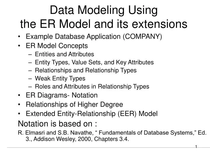
Data Modeling Using the ER Model and its extensions • Example Database Application (COMPANY) • ER Model Concepts • Entities and Attributes • Entity Types, Value Sets, and Key Attributes • Relationships and Relationship Types • Weak Entity Types • Roles and Attributes in Relationship Types • ER Diagrams- Notation • Relationships of Higher Degree • Extended Entity-Relationship (EER) Model Notation is based on : R. Elmasri and S.B. Navathe, “ Fundamentals of Database Systems,” Ed. 3., Addison Wesley, 2000, Chapters 3.4.
E1 SUMMARY OF ER-DIAGRAM NOTATION Symbol Meaning ENTITY TYPE WEAK ENTITY TYPE RELATIONSHIP TYPE IDENTIFYING RELATIONSHIP TYPE ATTRIBUTE KEY ATTRIBUTE MULTIVALUED ATTRIBUTE COMPOSITE ATTRIBUTE DERIVED ATTRIBUTE TOTAL PARTICIPATION OF E2 IN R CARDINALITY RATIO 1:N FOR E1:E2 IN R STRUCTURAL CONSTRAINT (min, max) ON PARTICIPATION OF E IN R R E2 N R E1 E2 (min,max) R E
Example COMPANY Database • Requirements of the Company (oversimplified for illustrative purposes) • The company is organized into DEPARTMENTs. Each department has a name, number and an employee who manages the department. We keep track of the start date of the departmentmanager. • Each department controls a number of PROJECTs. Each project has a name, number and islocated at a single location.
Example COMPANY Database (Cont.) • We store each EMPLOYEE’s social security number, address, salary, sex, and birthdate. Each employee works for one department but may work on several projects. We keep track of the number of hours per week that an employee currently works on each project. We also keep track of the direct supervisor of each employee. • Each employee may have a number of DEPENDENTs. For each dependent, we keep track of their name, sex, birthdate, and relationship to employee.
ER Model Concepts:Entities and Attributes • Entities - are specific objects or things in the mini-world that are represented in the database; for example, the EMPLOYEE John Smith, the Research DEPARTMENT, the ProductX PROJECT • Attributes are properties used to describe an entity; for example, an EMPLOYEE entity may have a Name, SSN, Address, Sex, BirthDate • A specific entity will have a value for each of its attributes; for example, a specific employee entity may have Name=‘John Smith’, SSN=‘123456789’, Address=‘731 Fondren, Houston, TX’, Sex=‘M’, BirthDate=‘09-JAN-55’
Types of Attributes • Simple: Each entity has a single atomic value for the attribute; for example SSN or Sex • Composite: The attribute may be composed of several components; for example, Address (Apt#, House#, Street, City, State, ZipCode, Country) or Name(FirstName, MiddleName, LastName). Composition may form a hierarchy where some components are themselves composite. • Multi-valued: An entity may have multiple values for that attribute; for example, Color of a CAR or PreviousDegrees of a STUDENT. Denoted as {Color} or {PreviousDegrees}. • In general, composite and multi-valued attributes may be nested arbitrarily to any number of levels although this is rare. For example, PreviousDegrees of a STUDENT is a composite multi-valued attribute denoted by {PreviousDegrees(College, Year, Degree, Field)}.
Entity Types and Key Attributes • Entities with the same basic attributes are grouped or typed into an entity type. For example, the EMPLOYEE entity type or the PROJECT entity type. • An attribute of an entity type for which each entity must have a unique value is called a key attribute of the entity type. For example, SSN of EMPLOYEE. • A key attribute may be composite. For example, VehicleTagNumber is a key of the CAR entity type with components (Number, State). • An entity type may have more than one key. For example, the CAR entity type may have two keys: • VehicleIdentificationNumber (popularly called VIN) and • VehicleTagNumber (Number, State), also known as license_plate number.
ENTITY TYPE CAR WITH ATTRIBUTES CAR Registration(RegistrationNumber, State), VehicleID, Make, Model, Year, (Color) car1 ((ABC 123, TEXAS), TK629, Ford Mustang, convertible, 1989, (red, black)) car2 ((ABC 123, NEW YORK), WP9872, Nissan Sentra, 2-door, 1992, (blue)) car3 ((VSY 720, TEXAS), TD729, Chrysler LeBaron, 4-door, 1993, (white, blue)) . . .
Relationships and Relationship Types • A relationship relates two or more distinct entities with a specific meaning; for example, EMPLOYEE John Smith works on the ProductX PROJECT or EMPLOYEE Franklin Wong manages the Research DEPARTMENT. • Relationships of the same type are grouped or typed into a relationship type. For example, the WORKS_ON relationship type in which EMPLOYEEs and PROJECTs participate, or the MANAGES relationship type in which EMPLOYEEs and DEPARTMENTs participate. • The degree of a relationship type is the number of participating entity types. Both MANAGES and WORKS_ON are binary relationships. • More than one relationship type can exist with the same participating entity types; for examples, MANAGES and WORKS_FOR are distinct relationships between EMPLOYEE and DEPARTMENT participate.
Weak Entity Types • An entity that does not have a key attribute • A weak entity must participate in an identifying relationship type with an owner or identifying entity type • Entities are identified by the combination of: • A partial key of the weak entity type • The particular entity they are related to in the identifying entity type Example: Suppose that a DEPENDENT entity is identified by the dependent’s first name and birhtdate, and the specific EMPLOYEE that the dependent is related to. DEPENDENT is a weak entity type with EMPLOYEE as its identifying entity type via the identifying relationship type DEPENDENT_OF
ABSTRACTION Classification Aggregation Identification Generalization ER Model Concept Entity Type- a grouping of member entities Relationship Type - a grouping of member relationships Relationship Typeis an aggregation of (over) its participating entity types Weak Entity Type ???????? ER Model and Data Abstraction
Constraints on Aggregation • Cardinality Constraints on Relationship Types • ( Also known as ratio constraints ) • Maximum Cardinality • One-to-one • One-to-many • Many-to-many • Minimum Cardinality (also called participation or existence dependency constraints) • zero (optional participation, not existence-dependent) • one or more (mandatory, existence-dependent)
One-to-many(1:N) or Many-to-one (N:1) RELATIONSHIP EMPLOYEE WORKS_FOR DEPARTMENT e1 e2 e3 e4 e5 e6 e7 r1 r2 r3 r4 r5 r6 r7 d1 d2 d3
MANY-TO-MANY(M:N)RELATIONSHIP r9 e1 e2 e3 e4 e5 e6 e7 r1 r2 r3 r4 r5 r6 r7 d1 d2 d3 r8
Structural Constraints – one way to express semantics of relationships Structural constraints on relationships: • Cardinality ratio (of a binary relationship): 1:1, 1:N, N:1, or M:N SHOWN BY PLACING APPROPRIATE NUMBER ON THE LINK. • Participation constraint (on each participating entity type): total (called existence dependency) or partial. SHOWN BY DOUBLE LINING THE LINK NOTE: These are easy to specify for Binary RelationshipTypes. Do not be misled by obscure notations to specify above constraints for higher order relationships
Alternative (min, max) notation for relationship structural constraints: • Specified on each participation of an entity type E in a relationship type R • Specifies that each entity e in E participates in at least min and at most max relationship instances in R • Default(no constraint): min=0, max=n • Must have minmax, min0, max 1 • Derived from the knowledge of mini-world constraints Examples: • A department has exactly one manager and an employee can manage at most one department. • Specify (0,1) for participation of EMPLOYEE in MANAGES • Specify (1,1) for participation of DEPARTMENT in MANAGES • An employee can work for exactly one department but a department can have any number of employees. • Specify (1,1) for participation of EMPLOYEE in WORKS_FOR • Specify (0,n) for participation of DEPARTMENT in WORKS_FOR
The (min,max) notation for higher order relationship type constraints (0,1) (1,1) Employee Department Manages (1,1) (1,N) Employee Department Works-for What does it mean to put m:n:p on the three arms of the relationship? It is essentially meaningless. The (min,max) notation “looking away” from the entity is the best to use.
Relationships of Higher Degree • Relationship types of degree 2 are called binary • Relationship types of degree 3 are called ternary and of degree n are called n-ary • In general, an n-ary relationship is not equivalent to n binary relationships
TERNARY RELATIONSHIPS © The Benjamin/Cummings Publishing Company, Inc. 1994, Elmasri/Navathe, Fundamentals of Database Systems, Second Edition
TERNARY VS. BINARY RELATIONSHIPS © The Benjamin/Cummings Publishing Company, Inc. 1994, Elmasri/Navathe, Fundamentals of Database Systems, Second Edition
TERNARY RELATIONSHIP- Instance Diagram SUPPLIER SUPPLY PROJECT s1 s2 r1 r2 r3 r4 r5 r6 r7 j1 j2 j3 PART p1 p2 p3
Problem with constraints on higher order relationship types m n Supplier Part Supplies p Project What does it mean to put m:n:p on the three arms of the relationship ? It is essentially meaningless.
The (min,max) notation for higher order relationship type constraints (1,2) Teacher (1,3) Course Offering (1,5) Student A Teacher can offer min 1 and max 2 Offerings A Course may have 1 to 3 Offerings A Student may enroll in from 1 to 5 Offerings
RECURSIVE RELATIONSHIP SUPERVISION EMPLOYEE WORKS_FOR e1 e2 e3 e4 e5 e6 e7 r1 r2 r3 r4 r5 r6 2 1 2 1 2 1 2 1 1 2 1 2 © The Benjamin/Cummings Publishing Company, Inc. 1994, Elmasri/Navathe, Fundamentals of Database Systems, Second Edition
Roles played by Entity Types in Relationship types • In a recursive relationship two entities of the same entity type are related; for example, a SUPERVISION relationship type relates one EMPLOYEE (in the role of supervisee) to another EMPLOYEE (in the role of supervisor). • Similarly, the same entity type may play different roles in different relationships. E.g., Employee plays the role • ATTRIBUTES OF RELATIONSHIP TYPES: • A relationship type can have attributes; for example, HoursPerWeek of WORKS_ON; its value for each relationship instance describes the number of hours per week that an EMPLOYEE works on a PROJECT.
Data Modeling Tools A number of popular tools that cover conceptual modeling and mapping into relational schema design. Examples: ERWin, S- Designer (Enterprise Application Suite), ER- Studio, etc. POSITIVES: serves as documentation of application requirements, easy user interface - mostly graphics editor support
Problems with Current Modeling Tools • DIAGRAMMING • Poor conceptual meaningful notation. • To avoid the problem of layout algorithms and aesthetics of diagrams, they prefer boxes and lines and do nothing more than represent (primary-foreign key) relationships among resulting tables.(a few exceptions) • METHODOLGY • lack of built-in methodology support. • poor tradeoff analysis or user-driven design preferences. • poor design verification and suggestions for improvement.
Some of the Currently Available Automated Database Design Tools
ER DIAGRAM FOR A BANK DATABASE © The Benjamin/Cummings Publishing Company, Inc. 1994, Elmasri/Navathe, Fundamentals of Database Systems, Second Edition
PROBLEM with ER notation THE ENTITY RELATIONSHIP MODEL IN ITS ORIGINAL FORM DID NOTSUPPORT THE GENERALIZATION ABSTRACTION.
Extended Entity-Relationship (EER) Model • Incorporates Set-subset relationships • Incorporates Generalization Hierarchies • LIMITATIONS OF THE ER MODEL: • No relationship may be defined between an entity type and a relationship type NEXT SECTION OF THIS Presentation ILLUSTRATES HOW THE ER MODEL CAN BE EXTENDED WITH - Set-subset relationships and Generalization Hierarchies and how we can impose further notation on them.