Download

1 / 13
140 likes | 336 Views
Tolerancing II Engr 135. Tolerancing Terminology. Basic Size The theoretical size used as a starting point the application of tolerances. Tolerance The acceptable dimensional variation that is permitted on a part. Limits Maximum and minimum size shown by the toleranced value 1.00 ±0.05

E N D
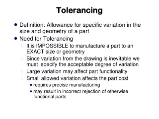
Tolerancing Terminology • Basic Size • The theoretical size used as a starting point the application of tolerances. • Tolerance • The acceptable dimensional variation that is permitted on a part. • Limits • Maximum and minimum size shown by the toleranced value • 1.00 ±0.05 • Upper limit = 1.05 • Lower limit = 0.95 • Allowance • The minimum clearance or maximum interference between two parts • Smallest hole – Largest Shaft
Tolerancing Terminology • Maximum Material Condition (MMC) • The condition when the part contains the most amount of material • For a shaft (external feature) this would be the upper limit • For a hole (internal feature) this would be the lower limit • Least Material Conditions (LMC) • The condition when the part contains the least amount of material • For a shaft (external feature) this would be the lower limit • For a hole (internal feature) this would be the upper limit
Tolerancing Terminology • Fits between parts • Clearance Fit (running fit) • A condition in which an internal part is smaller than the external part it fits into. • Hole is always larger than the shaft • Interference Fit (force fit) • A condition in which an internal part is larger than the external part it fits into. • Hole is always smaller than the shaft • Transitional Fit (locational fit) • The limits of size applied to a part can either result in a clearance fit or a transitional fit.
Fit Systems • Selective Assembly • An assembly method where the parts are measured and grouped into small, medium and large parts, all within tolerance. The groups are then assembled with similar matching parts of small, medium and large part for a better than random fit. • Basic Hole System • The basic hole system applies the basic size to the smallest hole. • Most used as there are limited standard tools for making holes • The allowance is applied to the shaft which can typically be made any size • Basic Shaft System • Used in the textile industry where many different parts fit on long shafts • Shaft is made nominal and holes are machined to fit to achieve the desired clearance or interference fit
Basic Hole System • Preferred Precision Fits • English unit tolerance relationships • ANSI Standard B4.1 • Specifies a series of standard fits between cylindrical parts • Fit Classes • Running and Sliding Fits (RC) • Clearance Locational Fits (LC) • Transitional Locational Fits (LT) • Interference Locational Fits (LN) • Force and Shrink Fits (FN)
Running and Sliding Clearance Fits • There are nine classes of running and sliding clearance fits. • Running and sliding clearance fits always provides a clearance between the shaft and the hole. • Smaller classes of fit (RC1 or RC2) provide less clearance than larger classes of fit (RC8 or RC9). • The amount of tolerance permitted by an RC fit is proportional to the size of the part.
Lecture Example • Determine the tolerances for a 3/4 in. shaft and hole using with RC3 class fit using the Basic Hole System. • Determine the nominal size of the hole and shaft. • Determine class of fit. • Locate the Clearance and Standard Tolerance Limits on the appropriate Tolerance Table. • Determine the maximum and minimum hole size by adding the tolerances to the nominal size of the hole. • Determine the maximum and minimum shaft size by adding the tolerances to the nominal size of the shaft.
Lecture Example • n 0.7500 Nominal Size • RC3 Class Fit • 0.71 – 1.19 Nominal Size Range in Tolerance Table • Minimum Clearance = 0.0008 • Maximum Clearance = 0.0021 • Tolerance on hole • +.0008 • -.0000 • Tolerance on the shaft • -.0008 • -.0013
Lecture Example (cont’d) • Maximum Hole Size = (.7500 + .0008) = .7508 • Minimum Hole Size = (.7500 + .0000) = .7500 • Maximum Shaft Size = (.7500 + -.0008) = .7492 • Minimum Shaft Size = (.7500 + -.0013) = .7487