Download
1 / 26
260 likes | 374 Views
Experimental Techniques for Polarized DIS and SIDIS. Sebastian Kuhn Old Dominion University (Norfolk, VA). Outline. Introduction Polarized beams Polarized targets Detector Elements Observables Analyzing Experiments with Polarization Corrections and Backgrounds Conclusion. Introduction.

E N D
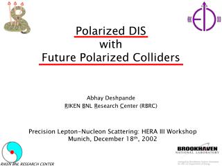
Experimental Techniques for Polarized DIS and SIDIS Sebastian Kuhn Old Dominion University (Norfolk, VA)
Outline • Introduction • Polarized beams • Polarized targets • Detector Elements • Observables • Analyzing Experiments with Polarization • Corrections and Backgrounds • Conclusion
Introduction 3-D Picture of parton flavor, spin and momentum (TMDs) • What would we LIKE to observe? p p S p H Traditional “1-D” Parton Distributions (PDFs) (inclusive, integrated over many variables) 3-D parton orbits (GPDs)
Introduction • What CAN we observe? [1] • Example: TMDs • Have 2 pseudoscalars (h, H), 2 vectors and 2 axial vectors • Observables depend on x (and Q2) and must be scalars! • 3 possibilities without : • 1 (ordinary PDFs ⇒ unpolarizedstructure function F1) • H.h (helicity PDFs ⇒ spin structure function g1) • (transversity PDFs/structure function h1) • 4 possibilities linear in : • , (“Worm gear” PDFs g1T, h1L⊥) • , (Sivers, Boer-Mulders PDFs f1T⊥, h1⊥) • Further possibilities quadratic in : • “Pretzelosity”h1T⊥ • k⊥ distributions of first three…
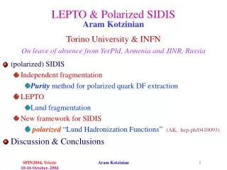
Introduction • What CAN we observe? [2] Electroweak Probe to “see” partons… g* g g* q q DIS ⇒ F1, g1 DVCS ⇒ GPDs …but we need extra hadrons to access all observables: PhT π Drell-Yan Hadron Production (e.g. @ RHIC) SIDIS
What Do we Need? • (Polarized) Beam • Electrons or muons → g*; pions, protons, antiprotons?... • (Polarized) Targets (or counterrotating beams) • Protons, deuterons, 3He [for n], antiprotons?... • Detectors • For scattered/produced electrons/muonsand hadronic debris • Need to distinguish e-/µ-/π-/K-… and e+/µ+/π+/K+/p…, measure g/n, reconstruct π0, h,… • Cover relatively large acceptance for both scattered particle and produced hadron/photon; usually require moderate kinematic resolution • Facilities
Accelerators Surf the microwaves! Accelerating cavity: disk loaded cylindrical wave guide use TM01 mode to get a longitudinal electric field match phase and velocity new old Jefferson Lab DESY
LHe Arcs Linac Accelerators – 2 Examples • Superconducting Linear Accelerators (CEBAF at JLab) • 2K niobium cavities, very low resistive losses • Recirculate few times, 100’s of µA • High gradient (5-50 MeV/m ⇒ 4-12 GeV) • CW extracted beam on external targets • Thick targets ⇒ high luminosity • Storage rings (HERA at DESY, RHIC at BNL) • Large circulating currents (mA) • Recirculate millions of times • Require only modest (re)acceleration • CW internal beam on thin gas targetsor counterrotating beams (typically lower Luminosity)
Polarized Electron Beams • List of Ingredients: • Circularly polarized laser light • Ti-Sapphire or Diode lasers • Polarizers, Pockel cell, /2 plate • Photocathode (Semiconductor covered by Alkalide, e.g. Cs) • Historically: Bulk GaAs (<50% Pol.) • Strained GaAs (breaks degeneracy of 2 energy levels) • State of the art: “Superlattice” - Thin GaAs on top of GaAsP (> 85% Pol.) • Beam transport • Wien filter - crossed E and B fields to rotate spin direction arbitrarily • Injection into main accelerator • Acceleration (account for precession) • Beam diagnostics (emittance, phase lock, polarization…) JLab polarized electron source
PolariMetry • Mott polarimeter (e-Nucleus scattering) at low energies (injector) • Spin-orbit coupling in electromagnetic interaction (electron magnetic moment “sees” current due to moving nuclear charge in its rest frame) • Møllerpolarimeter (e-e scattering) in experimental Hall; use magnetized iron foils (spin-polarized e’s) • Spin-spin coupling in electromagnetic interaction • Asymmetry can be calculated as function of electron energy and scattering angle from QED • Compton polarimeter - polarized laser light interacting with electrons • Similar to spin structure functions – electron can only absorb photon with opposite spin direction Quadrupoles 10” beam pipe Magnetized Fe target Don Jones, 2nd prize 2011 Poster Competition JLab UG meeting
Other Polarized Beams • Polarized muons: Create pion beam (proton-nucleus interaction), pions decay via weak interaction => muons are “naturally” polarized via parity violation in weak IA (select polarization kinematically). Example: CERN • Electrons and positrons in storage rings: Spin-dependent part of synchrotron radiation emission leads over timeto build-up of transverse polarization (Sokolov-Ternoveffect). Spin rotators at interaction points -> longitudinal polarization. Example: HERA/HERMES • Polarized protons: Atomic Beam sources (HFS of H, D…); avoid depolarizing resonances while accelerating! • More exotic: Polarized anti-protons (spin filters),…
Polarized Proton and Deuteron Solid Targets • List of Ingredients: • Polarizable Material (high H content) with paramagnetic centers = unpaired e- (irradiated or chemically doped) • Alcohols (e.g. butanol) • Ammonia - 15NH3 and 15ND3 • HD ice • (Very) Low Temperature • About 1 K for (continuous) dynamic polarization - pumped-on liquid 4He bath at low pressure • 100 mK or less for frozen spin mode - 3He/4He dilution refrigerator • Dynamic Polarization in high B-field • About 2.5 - 5 T -> unpaired e- 100% polarized • Polarization transferred to nuclei via HF transitions (simultaneous electron and nuclear spin flip); requires 70-140 GHz microwaves (few 100 mW) • Holding Field (for frozen spin mode; can be lower) • NMR system to monitor polarization • Insulation vacuum, beam and scattered particles ports Considerations: • Possibly significant “dilution” by “inactive” nuclei • Beam must be rastered to avoid local depolarization • Target must be annealed repeatedly to alleviate radiation damage (electron beam) • Total dose and current limitations (e.g., 100 nA max) • Transverse DNP targets -> large deflection of electrons
Polarized Proton and Deuteron Solid Targets Example: CLAS polarized NH3/ND3 target. Typical polarization 0.7-0.9 (p) and 0.3-0.4 (d)
Transverse Polarization? Top View Chicane system beam coil Goal: Let beam exit in horizontal direction B z Issue: Strong electromagnetic background from synchrotron radiation Acceptance: ΘTrans < 22.5 degree (forward cone) 55 < ΘTrans < 125 (transverse) ΘBendPlane ~ full coverage (except for support structure)
Other examples for Solid Targets • Future longitudinally polarized target for CLAS12 (11 GeV program at Jefferson Lab) • Horizontal 4He evaporation cryostat • 5 T B-field provided by central detector • SMC/COMPASS target – • Largest in the world • (3 cells with opposite polarization) • 3He – 4He dilution refrigerator (T~50mK) • 6LiD or NH3 50/90% polarization • 2.5 T solenoid
Other examples for Solid Targets – HD Ice Frozen solid of HD molecules Polarize (brute force) at 0.010 K and 15 T Store + transfer at 2K, run at 0.05K Advantage: little background material, can measure H and D simultaneously Disadvantage: Don’t know yet whether it will work with electron beam…
Polarized Proton and Deuteron Gas Jet Targets • Example: HERMES • Atomic Beam Source (Stern-Gerlach separator, HF transitions using RF circuits • Open storage cell to get densities of up to a few times 1014 nucleons/cm2 • Differential pumping system • Circulating beam
3He Rb Rb K K K K 3He Polarized 3He Targets (approx. Pol. Neutron)
Typical Detector Elements Wire chambers measure position (and angle) -HV (thin foil or wire grid) gas +HV (thin wires) -HV (thin foil or wire grid) charged particle • Charged particle passes through wire chamber and knocks out electrons from the gas. • Electrons drift in the E field to the cathode wire, colliding with gas molecules • Close to the wire, the mean free path times the electric field is large enough to ionize the gas molecules. Avalanche! • Read the signal on the cathode wire (time gives distance) • Similar: GasElectronMultipliers, µMEGAs,… Applications: VDC, Multi-layer drift chamber (track → ), TimeProjectionChamber
Typical Detector Elements • Scintillators: time (⇒ b⇒ particle type)and energy measurement • (typical resolution: down to 50-100 ps for plastic) • Typically a doped plastic or crystal (eg: Ge, NaI, BaF2) • Charged particle passes through scintillator (or neutral particle interacts) and excites atomic electrons. These de-excite and emit light. • Minimum energy loss (when βγ≈ 1) is dE/dx = 2 MeV/(g/cm2) • Cherenkov counter: threshold velocity measurement. • Typically an empty box with smoke (ie: a gas) and mirrors • Local light speed is v = 1/n < c • Particles travelling faster than v will emit Cherenkov light (an electromagnetic ‘sonic boom’) ⇒ threshold CC (yes/no) • The opening angle of the Cherenkov cone is related to the particle’svelocity ⇒ RingImagingCHerenkov(measure b⇒ particle type) • Also: TransitionRadiationDetector, …
Typical Detector Elements • Electromagnetic shower counters: • measure energy (also time), discriminate electrons and detect neutral particles • Electrons and photons passing through material shower • After one radiation length of material on average: • Electrons emit a bremsstrahlung photon • Photons convert to an electron/positron pair or Compton-scatter • After ≈10 radiation lengths, one e- or γ is now ~1000 particles • Simple design: alternating layers of lead (RL = 6 mm) and scintillant Higher resolution: Heavy metal glass (Pb glass, PbWO4) combine both • Particles shower in the lead • Charged particles deposit energy in the scintillant Also: Hadronic Calorimeter, µ counter…
High Resolution Spectrometers Jefferson Lab Hall A Typically small acceptance but high resolution, very good shielding (→ high luminosity)
Large Acceptance Detectors COMPASS HERMES
TOF CAL CER DC3 DC2 DC1 x x
Under construction; expected to begin data taking in 2015 with upgraded 11 GeV beam CLAS12 • Base equipment • Forward Detector • - TORUS magnet • - Forward vertex tracker • HT Cherenkov Counter • Drift chamber system • LT Cherenkov Counter • Forward ToF System • Preshower calorimeter • E.M. calorimeter • Central Detector • SOLENOID magnet • Barrel Silicon Tracker • Central Time-of-Flight Central Detector Forward Detector • Proposed equipment • Micromegas (CD & FD) • RICH counter (FD) • Neutron detector (CD) • Small angle tagger (FD) 2m