Download
1 / 28
1.29k likes | 5.54k Views
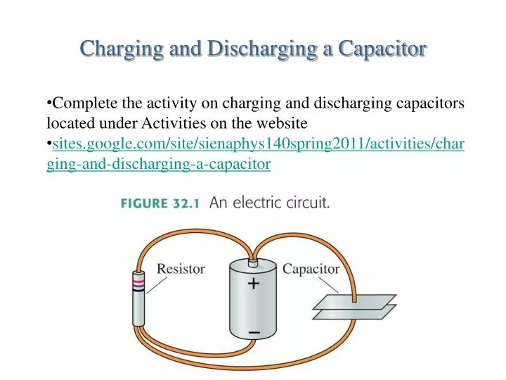
Charging and Discharging a Capacitor. Complete the activity on charging and discharging capacitors located under Activities on the website sites.google.com/site/sienaphys140spring2011/activities/charging-and-discharging-a-capacitor . Tactics: Using Kirchhoff’s loop law.

E N D
Charging and Discharging a Capacitor • Complete the activity on charging and discharging capacitors located under Activities on the website • sites.google.com/site/sienaphys140spring2011/activities/charging-and-discharging-a-capacitor
Energy and Power The power supplied by a battery is The units of power are J/s, or W. The power dissipated by a resistor is Or, in terms of the potential drop across the resistor
Series Resistors • Resistors that are aligned end to end, with no junctions between them, are called series resistors or, sometimes, resistors “in series.” • The current I is the same through all resistors placed in series. • If we have N resistors in series, their equivalent resistance is The behavior of the circuit will be unchanged if the N series resistors are replaced by the single resistor Req.
Parallel Resistors • Resistors connected at both ends are called parallel resistors or, sometimes, resistors “in parallel.” • The left ends of all the resistors connected in parallel are held at the same potential V1, and the right ends are all held at the same potential V2. • The potential differences ΔV are the same across all resistors placed in parallel. • If we have N resistors in parallel, their equivalent resistance is The behavior of the circuit will be unchanged if the N parallel resistors are replaced by the single resistor Req.
EXAMPLE 32.10 A combination of resistors QUESTION:
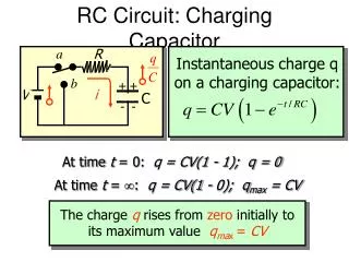
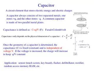
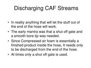
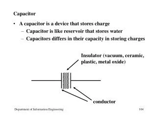
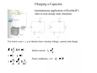
RC Circuits • Consider a charged capacitor, an open switch, and a resistor all hooked in series. This is an RC Circuit. • The capacitor has charge Q0 and potential difference ΔVC = Q0/C. • There is no current, so the potential difference across the resistor is zero. • At t = 0 the switch closes and the capacitor begins to discharge through the resistor. • The capacitor charge as a function of time is where the time constant τ is
Junction Rule Circuits
Resistance, Voltage • Determine (a) the equivalent resistance of the circuit and (b) the voltage across each resistor. Circuits
Rank in order of brightness • Rank bulbs 1 through 6 in order of descending brightness. • Brightness is proportional to power • Now assume the filament in B6 breaks. Again rank the bulbs in order of descending brightness. Circuits
Practice Problems • Determine the equivalent resistance and the current through R1 for the circuits shown. Assume R1 = 10, R2 = 20 , and R1 = 30 , and the battery is 12 V. Circuits
Activities • Exploration of Physics • E&M • Resistive circuits • Do each of the 5 circuits – set all to 50 ohms • Calculate I, V, and P for each resistor and then check answers in the program Current & Resistance