Download
1 / 81
940 likes | 1.35k Views
8051 Programming (Addressing Mode-Instruction Set) Lec note 5. Outline. Data transfer instructions Addressing modes Data processing (arithmetic and logic) Program flow instructions. Data Transfer Instructions. MOV dest, source dest source Stack instructions

E N D
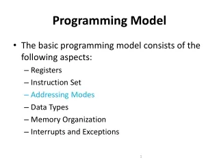
Outline • Data transfer instructions • Addressing modes • Data processing (arithmetic and logic) • Program flow instructions
Data Transfer Instructions • MOV dest, source dest source • Stack instructions PUSH byte ;increment stack pointer, ;move byte on stack POP byte ;move from stack to byte, ;decrement stack pointer • Exchange instructions XCH a, byte ;exchange accumulator and byte XCHD a, byte ;exchange low nibbles of ;accumulator and byte
Addressing Modes • Ways of accessing data • 8051 has different addressing mode: • Immediate (constant data) • Register (register data) • Direct (RAM data) • Register indirect (RAM data) • Indexed (ROM data) • relative addressing • Absolute addressing • Long addressing
Addressing Modes Immediate Mode– specify data by its value mov A, #0 ;put 0 in the accumulator ;A = 00000000 mov R4, #11h ;put 11hex in the R4 register ;R4 = 00010001 mov B, #11 ;put 11 decimal in b register ;B = 00001011 mov DPTR,#7521h ;put 7521 hex in DPTR ;DPTR = 0111010100100001
Addressing Modes Immediate Mode– continue MOV DPTR,#7521h MOV DPL,#21H MOV DPH, #75 COUNT EGU 30 ~ ~ mov R4, #COUNT MOV DPTR,#MYDATA ~ ~ 0RG 200H MYDATA:DB “IRAN”
Addressing Modes Register Addressing – either source or destination is one of CPU register MOV R0,A MOV A,R7 ADD A,R4 ADD A,R7 MOV DPTR,#25F5H MOV R5,DPL MOV R1,DPH Note that MOV R4,R7 is incorrect
Addressing Modes Direct Mode – specify data by its 8-bit address Usually for 30h-7Fh of RAM Mov a, 70h ; copy contents of RAM at 70h to a Mov R0,40h ; copy contents of RAM at 40h to a Mov 56h,a ; put contents of a at 56h Mov 0D0h,a ; put contents of a into PSW
Addressing Modes Direct Mode – play with R0-R7 by direct address MOV A,4 MOV A,R4 MOV A,7 MOV A,R7 MOV 7,2 MOV R7,R6 MOV R2,#5 ;Put 5 in R2 MOV R2,5 ;Put content of RAM at 5 in R2
Addressing Modes Register Indirect – the address of the source or destination is specified in registers Uses registers R0 or R1 for 8-bit address: mov psw, #0 ; use register bank 0 mov r0, #3Ch mov @r0, #3 ; M[3Ch] 3 Uses DPTR register for 16-bit addresses: mov dptr, #9000h ; dptr 9000h movx a, @dptr ; a M[9000h] Note that 9000h is an address in external memory
Addressing Modes Register Indexed Mode – source or destination address is the sum of the base address and the accumulator(Index) • Base address can be DPTR or PC mov dptr, #4000h mov a, #5 movc a, @a + dptr ;a M[4005]
Addressing Modes Register Indexed Modecontinue • Base address can be DPTR or PC ORG 1000h 1000 mov a, #5 • movc a, @a + PC ;a M[1008] • Nop • Lookup Table • MOVC only can readinternal code memory PC
Access to Accumulator • A register can be accessed by direct and register mode • This 3 instruction has same function with different code 0703 E500 mov a,00h 0705 8500E0 mov acc,00h 0708 8500E0 mov 0e0h,00h • Also this 3 instruction 070B E9 mov a,r1 070C 89E0 mov acc,r1 070E 89E0 mov 0e0h,r1
Access to SFRs • B – always direct mode - except in MUL & DIV 0703 8500F0 mov b,00h 0706 8500F0 mov 0f0h,00h 0709 8CF0 mov b,r4 070B 8CF0 mov 0f0h,r4 • P0~P3 – are direct address 0704 F580 mov p0,a 0706 F580 mov 80h,a 0708 859080 mov p0,p1 • Also other SFRs (pcon, tmod, psw,….)
SFRs Address All SFRs such as (ACC, B, PCON, TMOD, PSW, P0~P3, …) are accessible by name and direct address But both of them Must be coded as direct address
8051 Instruction Format • immediate addressing add a,#3dh ;machine code=243d • Direct addressing mov r3,0E8h ;machine code=ABE8
8051 Instruction Format • Register addressing 070D E8 mov a,r0 ;E8 = 1110 1000 070E E9 mov a,r1 ;E9 = 1110 1001 070F EA mov a,r2 ;EA = 1110 1010 0710 ED mov a,r5 ;ED = 1110 1101 0711 EF mov a,r7 ;Ef = 1110 1111 0712 2F add a,r7 0713 F8 mov r0,a 0714 F9 mov r1,a 0715 FA mov r2,a 0716 FD mov r5,a 0717 FD mov r5,a
8051 Instruction Format • Register indirect addressing mov a, @Ri ; i = 0 or 1 070D E7 mov a,@r1 070D 93 movc a,@a+dptr 070E 83 movc a,@a+pc 070F E0 movx a,@dptr 0710 F0 movx @dptr,a 0711 F2 movx @r0,a 0712 E3 movx a,@r1
07FEh 8051 Instruction Format • relative addressing here: sjmp here ;machine code=80FE(FE=-2) Range = (-128 ~ 127) • Absolute addressing (limited in 2k current mem block) 0700 1 org 0700h 0700 E106 2 ajmp next ;next=706h 0702 00 3 nop 0703 00 4 nop 0704 00 5 nop 0705 00 6 nop 7 next: 8 end
8051 Instruction Format • Long distance address Range = (0000h ~ FFFFh) 0700 1 org 0700h 0700 020707 2 ajmp next ;next=0707h 0703 00 3 nop 0704 00 4 nop 0705 00 5 nop 0706 00 6 nop 7 next: 8 end
pop push stack pointer stack Stacks Go do the stack exercise…..
Stack • Stack-oriented data transfer • Only one operand • SP is other operand (register indirect – implied) • Direct addressing mode must be mov sp, #0x40 ; Initialize SP push 0x55 ; SP SP+1, M[SP] M[55] ; M[41] M[55] pop b ; b M[55] Note: can only specify RAM or SFRs (direct mode) to push or pop. Therefore, to push/pop the accumulator, must use Acc, (not A)
Stack (push,pop) • Therefore Push a ;is invalid Push r0 ;is invalid Push r1 ;is invalid push acc ;is correct Push psw ;is correct Push b ;is correct Push 13h Push 0 Push 1 Pop 7 Pop 8 Push 0e0h ;acc Pop 0f0h ;b
Exchange Instructions two way data transfer XCH a, 30h ; a M[30] XCH a, R0 ; a R0 XCH a, @R0 ; a M[R0] XCHD a, R0 ; exchange “digit” a[7..4] a[3..0] R0[7..4] R0[3..0] Only 4 bits exchanged
Bit-Oriented Data Transfer • transfers between individual bits. • Carry flag (C) (bit 7 in the PSW) is used as a single-bit accumulator • RAM bits in addresses 20-2F are bit addressable mov C, P0.0 mov C, 67h mov C, 2ch.7
SFRs that are Bit Addressable SFRs with addresses ending in 0 or 8 are bit-addressable. (80, 88, 90, 98, etc) Notice that all 4 parallel I/O ports are bit addressable.
Data Processing Instructions Arithmetic Instructions Logic Instructions
Arithmetic Instructions • Add • Subtract • Increment • Decrement • Multiply • Divide • Decimal adjust
ADD Instructions add a, byte ; a a + byte addc a, byte ; a a + byte + C • These instructions affect 3 bits in PSW: • C = 1 :if result is greater than FF • AC = 1 :if there is a carry out of bit 3 • OV = 1 :if there is a carry out of bit 7, but not from bit 6, or visa versa.
mov a, #3Fh add a, #D3h What is the value of the C, AC, OV flags after the second instruction is executed? ADD Examples 0011 1111 1101 0011 0001 0010 C = 1 AC = 1 OV = 0
Signed Addition and Overflow 0111 1111 (positive 127) 0111 0011 (positive 115) 1111 0010 (overflow cannot represent 242 in 8 bits 2’s complement) 2’s complement: 0000 0000 00 0 … 0111 1111 7F 127 1000 0000 80 -128 … 1111 1111 FF -1 1000 1111 (negative 113) 1101 0011 (negative 45) 0110 0010 (overflow) 0011 1111 (positive) 1101 0011 (negative) 0001 0010 (never overflows)
8-Bit Add Example ; Computes Z = X + Y ; Adds values at locations 78h and 79h and puts them in 7Ah ;------------------------------------------------------------------ X equ 78h Y equ 79h Z equ 7Ah ;----------------------------------------------------------------- org 00h ljmp Main ;----------------------------------------------------------------- org 100h Main: mov a, X add a, Y mov Z, a end
The 16-bit Add example ; Computes Z = X + Y (X,Y,Z are 16 bit) ;------------------------------------------------------------------ X equ 78h Y equ 7Ah Z equ 7Ch ;----------------------------------------------------------------- org 00h ljmp Main ;----------------------------------------------------------------- org 100h Main: mov a, X add a, Y mov Z, a mov a, X+1 adc a, Y+1 mov Z+1, a end
Subtract Example: SUBB A, #0x4F ;A A – 4F – C Notice that There is no subtraction WITHOUT borrow. Therefore, if a subtraction without borrow is desired, it is necessary to clear the C flag. Example: Clr c SUBB A, #0x4F ;A A – 4F
Increment and Decrement • The increment and decrement instructions do NOT affect the C flag. • Notice we can only INCREMENT the data pointer, not decrement.
Example: Increment 16-bit Word • Assume 16-bit word in R3:R2 mov a, r2 add a, #1 ; use add rather than increment to affect C mov r2, a mov a, r3 addc a, #0 ; add C to most significant byte mov r3, a
Multiply When multiplying two 8-bit numbers, the size of the maximum product is 16-bits FF x FF = FE01 (255 x 255 = 65025) MUL AB;BA A * B Note : B gets the High byte A gets the Low byte
Division Integer Division DIV AB ; divide A by B A Quotient (A/B) B Remainder(A/B) OV : indicates divide by zero C : set to zero
Decimal Adjust DA a; decimal adjust a Used to facilitate BCD addition. Adds “6” to either high or low nibble after an addition to create a valid BCD number. Example: mov a, #23h mov b, #29h add a, b ;a 23h + 29h = 4Ch (wanted 52) DA a ;a a + 6 = 52
Logic Instructions Bitwise logic operations (AND, OR, XOR, NOT) Clear Rotate Swap Logic instructions do NOT affect the flags in PSW
Bitwise Logic Examples: ANL AND ORL OR XRL XOR CPL Complement 00001111 10101100 ANL 00001100 00001111 10101100 ORL 10101111 00001111 10101100 XRL 10100011 10101100 CPL 01010011
Address Modes with Logic a, byte direct, reg. indirect, reg, immediate byte, a direct byte, #constant a ex: cpl a ANL – AND ORL – OR XRL – eXclusive oR CPL – Complement
Uses of Logic Instructions • Force individual bits low, without affecting other bits. anl PSW, #0xE7 ;PSW AND 11100111 • Force individual bits high. orl PSW, #0x18 ;PSW OR 00011000 • Complement individual bits xrl P1, #0x40 ;P1 XRL 01000000
Other Logic Instructions CLR - clear RL – rotate left RLC – rotate left through Carry RR – rotate right RRC – rotate right through Carry SWAP – swap accumulator nibbles
CLR ( Set all bits to 0) CLR A CLR byte (direct mode) CLR Ri (register mode) CLR @Ri (register indirect mode)
Rotate • Rotate instructions operate only on a RL a Mov a,#0xF0 ; a 11110000 RR a ; a 11100001 RR a Mov a,#0xF0 ; a 11110000 RR a ; a 01111000