Download
1 / 41
410 likes | 874 Views
Data Transport Networks - Wide Area Networks . Rong Wang CGS3285 Spring2004. RECOMMENDED READING. From textbooks: Chapter 18 and 19 of Data Communications and Networking, 3rd Edition, Behrouz A. Forouzan (ISBN: 0-07-251584-8)

E N D
Data Transport Networks- Wide Area Networks Rong Wang CGS3285 Spring2004
RECOMMENDED READING • From textbooks: • Chapter 18 and 19 ofData Communications and Networking, 3rd Edition, Behrouz A. Forouzan (ISBN: 0-07-251584-8) • Chapter 8 of Data Communications: From Basics to Broadband, 3rd Edition by William J. Beyda (ISBN: 0-13-096139-6)
Wide Area Networks • Switched communication networks • Circuit switching and telephone network • Packet switching principles • X.25 and Frame Relay • ATM
SWITCHED COMMUNICATION NETWORKS • Long distance transmission is typically done over a network of switched nodes • Nodes not concerned with content of data • End devices are stations • Computer, terminal, phone, etc. • A collection of nodes and connections is a communications network • Data routed by being switched from node to node
NODES • Nodes may connect to other nodes only, or to stations and other nodes • Node to node links usually multiplexed • Network is usually partially connected • Some redundant connections are desirable for reliability • Two different switching technologies • Circuit switching • Packet switching
SIMPLE SWITCHED NETWORK 2 3 1 5 6 4 7
CIRCUIT SWITCHING NETWORKS • Dedicated communication path between two stations • Three phases • Circuit Establishment • Data Transfer • Circuit Disconnect • Must have switching capacity and channel capacity to establish connection • Switches must have intelligence to work out routing
CIRCUIT SWITCHING - APPLICATIONS • Inefficient • Channel capacity dedicated for duration of connection • If no data, capacity wasted • Set up (connection) takes time • Once connected, transfer is transparent • Developed for voice traffic (phone)
PUBLIC CIRCUIT SWITCHED NETWORK Circuit switch Also Central office A telephone system Also Toll office
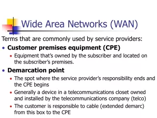
TELECOMMS COMPONENTS • Subscriber • Devices attached to network (e.g, telephone) • Subscriber line • Local Loop or subscriber loop • Connection to network • Few km up to few tens of km • Exchange • Switching centers, (e.g., tandem office) • End office - supports subscribers (e.g. central office) • Trunks • Branches between exchanges (e.g. interoffice trunk, intertoll trunk) • Multiplexed (TDM or FDM)
PACKET SWITCHING PRINCIPLES • Circuit switching designed for voice • Resources dedicated to a particular call • Disadvantages of circuit switching • Much of the time a data connection is idle • Data rate is fixed • Both ends must operate at the same rate
BASIC OPERATION • Messages/Files broken down into data packets • aka, datagrams, frames, packets • Typically 1000 octets • Each packet encapsulated with header and error control information (e.g., checksum, CRC) • Control Info • Header contains source & destination addresses • Packets passed to network which routes to destination address • Routing taken care of by packet network • Packets are received, stored briefly (buffered) and past on to the next node: Store and forward • Network includes series of nodes • Packets can follow different routes to destination
SWITCHING TECHNIQUE • Station breaks long message into packets • Packets sent one at a time to the network • Packets handled in two ways • Datagram • Virtual circuit
DATAGRAM • Each packet treated independently • Packets can take any practical route • Packets may arrive out of order • Packets may go missing • Up to receiver to re-order packets and recover from missing packets
DATAGRAM DIAGRAM • Often used in network layer • Each packet (referred to datagram) is treated independently of all others • Does not need to call setup • This approach can cause datagrams of a transmission to arrive at their destination out of order • Switching at the network layer in the Internet is done using the datagram approach to packet switching
VIRTUAL CIRCUIT • Often used in data link layer • Preplanned route established before any packets sent • Call request and call accept packets establish connection (handshake) • Each packet contains a virtual circuit identifier (VCI) instead of destination address • No routing decisions required for each packet • Clear request to drop circuit • Not a dedicated path
VIRTUAL CIRCUIT IDENTIFIER • A small number that only has switch scope • Used by a frame between two switches • When a frame arrives at a switch, it has one VCI • When a frame leaves, it has another VCI
VCI PHASES • To communicate, a source and destination need to go through three phases • Setup • Data transfer • Connection tear down
SETUP PHASE – SETUP REQUEST • A setup request is sent from source to destination, following entries can be determined: • Imcoming port • Outgoing port • Incoming VCI
SETUP PHASE – SETUP ACKNOWLEDGEMENT • A special frame, called the acknowledgment frame, can complete the entries in the switching tables
VIRTUAL CIRCUIT VS DATAGRAM • Virtual circuits • Network can provide sequencing and error control • Packets are forwarded more quickly • No routing decisions to make • Less reliable • Loss of a node looses all circuits through that node • Datagram • No call setup phase • Better if few packets • More flexible • Routing can be used to avoid congested parts of the network
ADVANTAGES OF PACKET SWITCHING • Easy access: • Dedicated access or dial up ports • Protocol conversion performed by PADs • Packet Assemblers/Disassemblers • Flexible: Virtual Circuits • Variable destinations (changing VCs like circuit switching) • Single fixed destination (simulates dedicated connection) • Reliable: • Flexible routing • Error checking • Efficient: • Single node to node link can be shared by many packets over time • Packets queued and transmitted as fast as possible • High speed at lower price (per packet charges may apply) • Shared resources and physical transmission media
ADVANTAGES OF PACKET SWITCHING (cont’d) • Data rate conversion • Each station connects to the local node at its own speed • Nodes buffer data if required to equalize rates • Packets are accepted even when network is busy • Delivery may slow down • Priorities can be used • Ease of maintenance: administered by PPSN providers
CIRCUIT VS PACKET SWITCHING • Performance • Propagation delay • Time it takes a signal to propagate from one node to the next • Transmission time • The time it takes for a transmitter to send out a block of data • Node delay • The time it takes for a node to perform the necessary processing as it switches data
X.25 PACKET SWITCHING • 1976 • X.25 one of the earliest PPSNs (Public Packet Switching Networks) • Interface between host and packet switched network • Generally, X.25 refers to the interface from synchronous DTE into the network (DCE): • Packet level (OSI Network Layer 3) • User data and control info are combined into packets here. Addressing info included in packet header • Frame level (OSI Data Link Layer 2) • Uses LAP-B protocol (Link Access Procedure-Balanced). Similar to SDLC. Packet error detection/correction • Physical level (OSI Physical Layer 1) • RS232C (also known as V.24) synchronous, full duplex • X.28 defines interface from async DTE to network PAD
FRAME RELAY NETWORKS • Designed to be more efficient than X.25 • Developed before ATM • Larger installed base than ATM • ATM now of more interest on high speed networks
FRAME RELAY NETWORKS • Relies on digital links between users and nodes • Therefore assumes near error-free transmission • Error checking not performed by nodes • Must be performed end-to-end by source and destination DTE in higher protocol layers • Operates only at Layers 1 and 2 of OSI model • Link Access Protocols (LAPD, LAPF) • Nodes merely “relay” frames (packets) • No need to open packets and inspect content for errors • Route may vary based on network status • Result is faster transmission of packets due to lower processing time at each node
ADVANTAGES AND DISADVANTAGES • Lost link by link error and flow control • Increased reliability makes this less of a problem • Streamlined communications process • Lower delay • Higher throughput • ITU-T recommend frame relay above 2Mbps
ATM NETWORKS • Asynchronous Transfer Mode • ATM Forum, founded 1991 • Carries all types of traffic • Data & Fax • Real Time Voice & Video • Fixed sized data packages, called "cells” • 53 octets (bytes) - (5 byte Header / 48 byte Payload) • Very high speed connections • Up to T3 (45 Mbps) • Fiber is preferred transmission media
ATM NETWORKS (cont.) • “Asynchronous” related to arrival rate of next cell, not physical transmission of bits • To make data stream more predictable, use idle bits or idle cells • Data inserted into continuous stream as needed. • Supports two header types • User-Network Interface-UNI • Network-Network Interface - NNI • Headers contain one of two identifier types • Virtual Channel Identifier - VCI • Virtual Path Identifier - VPI
TP, VPs and VCs • Connection between two endpoints is accomplished through transmission paths (TPs), virtual paths (VPs), and virtual circuits (VCs). • TP • Physical connection (write, cable, statellite, and so on) • VP • Provide a connection or a set of connection between two switches • VC • A single message path between source and destination
EXAMPLE OF VPS AND VCS • Note that a virtual connection is defined by a pair of numbers: the VPI and the VCI.
AN ATM CELL An ATM cell Header format
ATM ROUTING • Cells are “self routing” • Virtual channel/path determined during call setup • Same channel/path for all cells • Routing tables in each node in path updated with next node address • When cell reaches a node: • Node retrieves channel/path identifier from cell header • Looks up identifier routing table to get next node in path • Sends cell out port associated with next node • May modify header along the way if necessary • Routing method and high speed physical links allow use with real time, isochronous data: • Cells arrive at destination in order of sending • Cells arrive at destination at rate comparable to sending
LAYERS OF ATM • ATM Adaptation Layer • breaks information into 48 octet blocks • ATM Layer • adds 5 octet header with routing information • Physical layer • groups multiple cells into a payload envelope, adds framing and maintenance information and sends data