Download
1 / 34
590 likes | 1.47k Views
High-Level Data Link Control (HDLC). HDLC was defined by ISO for use on both point-to-point and multipoint data links. It supports full-duplex communication Other similar protocols are Synchronous Data Link Control (SDLC) by IBM Advanced Data Communication Control Procedure (ADCCP) by ANSI

E N D
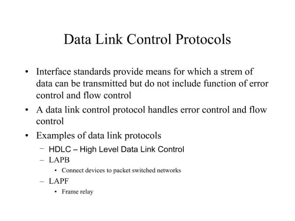
High-Level Data Link Control (HDLC) • HDLC was defined by ISO for use on both point-to-point and multipoint data links. • It supports full-duplex communication • Other similar protocols are • Synchronous Data Link Control (SDLC) by IBM • Advanced Data Communication Control Procedure (ADCCP) by ANSI • Link Access Procedure, Balanced (LAP-B) by CCITT, as part of its X.25 packet-switched network standard
HDLC Overview Broadly HDLC features are as follows: • Reliable protocol • Full-duplex communication • receive and transmit at the same time • Bit-oriented protocol • use bits to stuff flags occurring in data • Flow control • adjust window size based on receiver capability • Uses physical layer clocking and synchronization to send and receive frames
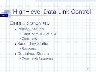
HDLC Overview • Defines three types of stations • Primary • Secondary • Combined
Primary station • Has the responsibility of controlling the operation of data flow the link. • Handles error recovery • Frames issued by the primary station are called commands.
Secondary station, • Operates under the control of the primary station. • Frames issued by a secondary station are called responses. • The primary station maintains a separate logical link with each secondary station.
Combined station, • Acts as both as primary and secondary station. • Does not rely on other for sending data
HDLC Unbalanced Mode Commands Primary Responses Secondary Secondary Balanced mode Combined Combined commands/Responses
Defines three types of data transfer mode • Normal Response mode • Asynchronous Response mode • Asynchronous Balanced mode
HDLC • Three modes of data transfer operations
Normal Response Mode (NRM) • Mainly used in terminal-mainframe networks. In this case, • Secondaries (terminals) can only transmit when specifically instructed by the primary station in response to a polling • Unbalanced configuration, good for multi-point links
Asynchronous Response Mode (ARM) • Same as NRM except that the secondaries can initiate transmissions without direct polling from the primary station • Reduces overhead as no frames need to be sent to allow secondary nodes to transmit • Transmission proceeds when channel is detected idle , used mostly in point-to-point-links
Asynchronous Balanced Mode (ABM) • Mainly used in point-to-point links, for communication between combined stations
Non-operational Modes • Normal Disconnected Mode • Asynchronous Disconnected Mode Both the above modes mean that the secondary node is logically disconnected from the primary node • Initialization Mode • A node negotiates transmission parameters with the other node E.g., flow control information • Parameters negotiated in this mode are used during any of the data transfer modes
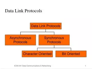
Frame Structure • Synchronous transmission • All transmissions in frames • Single frame format for all data and control exchanges
Frame Structure Defines 3 types of frames (I,S,U frames) 01111110 01111110
Flag Fields • Delimit frame at both ends • 01111110 • Receiver hunts for flag sequence to synchronize • Bit stuffing used to avoid confusion with data containing 01111110 • The transmitter inserts 0 bit after every sequence of five 1s with the exception of flag fields • If receiver detects five 1s it checks next bit • If 0, it is deleted • If 1 and seventh bit is 0 (i.e., 10), accept as flag • If sixth and seventh bits 1 (i.e., 11), sender is indicating abort
Data Link Control HDLC frame structure (a) Frame Format (b) Control field format
Address Field • Identifies secondary station that sent or will receive frame • Usually 8 bits long • May be extended to multiples of 7 bits • LSB of each octet indicates that it is the last octet (1) or not (0) • All ones (11111111) is broadcast
Cont. • Address field: • mainly used in multidrop link configuration, and not used in point-to-point • In unbalanced configuration, every secondary is assigned a unique address. Contains address of secondary station in both command and response frames • In balanced mode, command frame has destination address and response frame has sending node’s address • Group addresses are also possible. E.g., One command sent to all the secondaries
Control Field • Different for different frame type • I-frame (information frame) • data to be transmitted to user (next layer up) • Flow and error control piggybacked on information frames • S-frame (Supervisory frame) • Used for flow and error control • U-frame (Unnumbered frame) • supplementary link control • First one or two bits of control filed identify frame type
Poll/Final Bit • Use depends on context • Command frame • P bit : used for poll from primary • 1 to solicit (poll) response from peer • Response frame • F bit : used for response from secondary • 1 indicates response to soliciting command
Three types of frames • Unnumbered • information • Supervisory
HDLC • There are three different classes of frames used in HDLC • Unnumbered frames, used in link setup and disconnection, and hence do not contain ACK. • Information frames, which carry actual information. Such frames can piggyback ACK in case of ABM • Supervisory frames, which are used for error and flow control purposes and hence contain send and receive sequence numbers
HDLC • There are four different supervisory frames • SS=00, Receiver Ready (RR), and N(R) ACKs all frames received up to and including the one with sequence number N(R) - 1 • SS=10, Receiver Not Ready (RNR), and N(R) has the same meaning as above • SS=01, Reject; all frames with sequence number N(R) or higher are rejected, which in turns ACKs frames with sequence number N(R) -1 or lower. • SS=11, Selective Reject; the receive rejects the frame with sequence number N(R)
HDLC • The unnumbered frames can be grouped into the following categories: • Mode-setting commands and responses • Recovery commands and responses • Miscellaneous commands and responses
I-frame • Contains the sequence number of transmitted frames and a piggybacked ACK 1 2 3 4 5 6 7 8 0 N(S) P/F N(R) • I,0,0 • I,1,0 • I,2,0,P
S-frame • Used for flow and error control 1 2 3 4 5 6 7 8 1 0 S P/F N(R) • RR --- receive ready • RNR --- receive not ready • REJ --- reject on frame N(R) • SREJ --- selective reject on N(R)
U-frame • Mode setting, recovery, connect/diconnect 1 2 3 4 5 6 7 8 1 1 M P/F M Unnumbered function bits
Frame Check Sequence Field • FCS • Error detection • 16 bit CRC • Optional 32 bit CRC
HDLC Operation • Exchange of information, supervisory and unnumbered frames • Three phases • Initialization • Data transfer • Disconnect