Download
1 / 15
150 likes | 248 Views
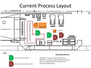
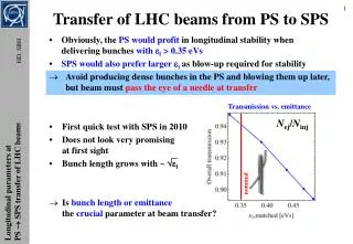
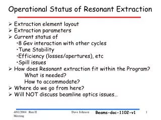
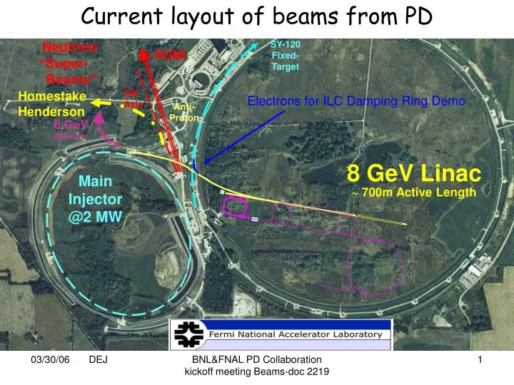
SY-120 Fixed-Target. 8 GeV Linac. 8 GeV neutrino. ~ 700m Active Length. Main Injector @2 MW. Current layout of beams from PD. Neutrino “Super- Beams”. NUMI. Homestake Henderson. Off- Axis. Electrons for ILC Damping Ring Demo. Anti- Proton.

E N D
SY-120 Fixed-Target 8 GeV Linac 8 GeV neutrino ~ 700m Active Length Main Injector @2 MW Current layout of beams from PD Neutrino “Super- Beams” NUMI Homestake Henderson Off- Axis Electrons for ILC Damping Ring Demo Anti- Proton BNL&FNAL PD Collaboration kickoff meeting Beams-doc 2219
Current Status of PD H- Transport and Injection • The basis of the current transport line and injection scheme started with the design concepts and transport/ collimation/ injection issues discussed in the 2004 H- Beam Transport Workshop at FNAL ! • Control of stripping losses in transport line (coll. , bb, lorentz) • Uncontrolled losses during injection • Foil issues (material, thickness, support, efficiency, etc) • Started addressing some of the Recommendations of the PD Directors Review last April • Re-examine the injection region layout, incorporating information on existing magnet dimensions, both interior and exterior, and verify a feasible design. • Evaluate collimation inefficiency and estimate the fractional “foil misses” that result. • Design the injection region and injection dump transport line to accommodate beam particles that miss the foil • Do a preliminary design and cost estimate for a beam tube liner • Conduct a one-day mini-review of the transfer line and MI injection. • Revisit the injection dump power handling capability… • Further optimize Linac pulse length (cost and performance) BNL&FNAL PD Collaboration kickoff meeting Beams-doc 2219
Current Status of PD H- Transport • Transport line • Focus on creating a sound optical design that minimizes civil construction conflicts – very close to end foot-print • Basic layout remains a 60 degree FODO lattice with two bend sections and matching section to the Linac and Ring. • Arcs are now achromatic: Field in arc dipoles 550G -> (fractional loss/m ~7.5E-9 -> at 1.54E14/1.5s -> 7.5E5 /m/s • Each Arc contains 30 dipoles • Re-use old MR B2 dipoles (2”x4”aperture) • 57 run DC on a single bus (air cooled) • first first three ramp to select beam MI/dump • Entire line contains 51 quads (new 1.3 m , 3” (?) pole tip) • 18 on QF and 19 on QD buss at +/- 10.0 kG/m (260G @1”) • 3 + last linac quad individual supplies @ max gradient 13 kG/m (current linac quad at ~31 kG/m • 11 individual quads to match from arc and 6 (8) to match into MI ( RR) • At bmax=75m 3s ~4.2 mm max Dispersion 6m -> 6 mm offset for dp/p of .001 BNL&FNAL PD Collaboration kickoff meeting Beams-doc 2219
Current Status of PD H- Transport • Transport line (continued) • The basic betatron and momentum collimation scheme has been retained (~similar to SNS) • 3 foil/ in-line absorber combinations in each plane for betatron collimation • Configuration: Foil in front of quad strips halo– absorber next half cell intercepts halo • b(foil) 75m b(absorber)30m • ~5 mm separation at absorber (need additional tracking verification) • Provision for two momentum collimation stations • b(foil) 75m b(absorber)50m • ~3-4mm separation at absorber (need additional tracking verification) • Current thought to use only 1 momentum collimation station • Need simulation which includes stripping and tracking both species of particles BNL&FNAL PD Collaboration kickoff meeting Beams-doc 2219
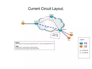
MI match match momentum momentum b’tron 8 Gev H- Transport to Main Injector De-buncher BNL&FNAL PD Collaboration kickoff meeting Beams-doc 2219
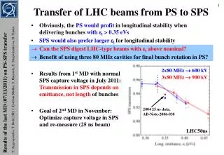
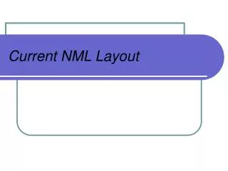
Dump 5 Dump 1 Dump 6 Dump2 Dump 3 Dump 7 Dump 8 Dump 4 Beam Collimation Results generated by A.Drozhdin for previous beam line version Dec 10 2004. Left side figures: 3-sigma core of the beam (green) and beam without collimation (red). Right side figures: beam population after collimation at every 60 degree (red) and intercepted halo at the beam dumps (green). BNL&FNAL PD Collaboration kickoff meeting Beams-doc 2219
MI H- Injection • Main Injector lattice for H- injection was re-designed • Converted FODO lattice (15 m space between quads) to symmetric straight with a 32 m space between doublets to be used for injection • Requires six new power supplies for local matching and adding trim coil circuits to IQC and IQD quads globally • Removed quad from injection straight (increase aperture, decouple inj. from tune quad bus) • Utilize wide aperture DC dipole for merging H- with protons (part of the chicane) • Utilize strong 1.2T short dipole after foil to strip excited states of H0 up to n=-2 and strip any H- miss • Place foil in rising field gradient of third magnet • Last chicane magnet place the injected protons on closed orbit and (with secondary foil) send H0->H+ to injection dump • Use horizontal painting (in MI) and vertical injection angle to produce “uncorrelated” beam distribution (A. Drozhdin) • Injection straight solid design – intend further optimization BNL&FNAL PD Collaboration kickoff meeting Beams-doc 2219
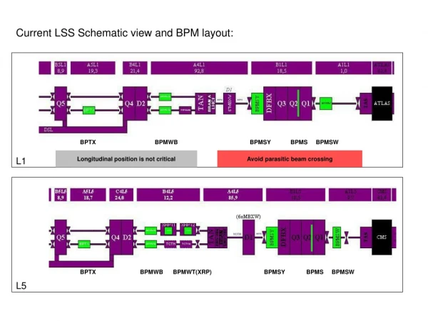
1.2T 558G Current MI10 foil H- H+ inj absorber H0 ,H- start end closed orbit (DC bumps) Painting trims MI10 for PD H- injection 32 m MI-10 Configuration for 8 Gev H- Injection Foil in front on 1.2T field • Generated toy MI lattice (without sextupoles or errors) to match existing MI lattice • Beta functions tunable in range of 20-60 m (both planes) used existingMI quads • Transfer PD optics to real MI lattice H- BNL&FNAL PD Collaboration kickoff meeting Beams-doc 2219
30.3 mm 16.7 mm 12.8 mm 3.03 mm DC Bump 110 mm 13.6 mm End Paint 146.4 mm Start Paint 160 mm 160 mm 110 mm MI CL 0 mm Painting scheme bx = 40m ax = 0 by = 20m ay = 0 36.4 mm Position of beam at start of painting (green), end of painting (red), and circulating beam (magenta). The optimum waveform: JHF Accelerator design study report. KEK Implemented by A. Drozhdin BNL&FNAL PD Collaboration kickoff meeting Beams-doc 2219
First Results for 270 turn Injection • Program STRUCT results (A. Drozhdin, et. al) • First result (preliminary) for 270 inj. tracking with new insert • Turn 10-100-270-277 • Left x-x’ / Right y-y’ • X 10mm/div • Y 5 mm/div • 270,000 particles • Track 27,000 particles • Lost 56 particles (7E-6 watts) -> 26kW in 3km • Foil hits/particle ~25 • Need to double check parameters • Clearly Needs Optimization BNL&FNAL PD Collaboration kickoff meeting Beams-doc 2219
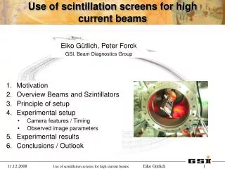
Lifetime of Stark states of H0 Field seen by H0* H- missed foil • Data for lifetime of Stark states of 8 Gev H0 as a function of magnetic field corresponding to its rest frame electric field see by the atom. • Calculations were done by W.Chou, Alexandr Drozhdin and presented at the 2004 Workshop • Path length for 1E-11 sec is approx 3 mm in lab frame • For 2” fringe field -> 23.6T/m gradient -> Dq ~7mr BNL&FNAL PD Collaboration kickoff meeting Beams-doc 2219
Lorentz Stripping • Using expression from L.Scherk for rest frame lifetime of H- in applied magnetic field. • Calculate lab frame lifetime (bgt) and stripping length (bgct) at fields in Chicane • Fields encountered after foil the stripping length is on the order of mm or less and the lifetime (lab frame) on the order of E-11. • Calculations Extrapolated from data 200 and 800 Mev .44 s BNL&FNAL PD Collaboration kickoff meeting Beams-doc 2219
Outstanding Issues • Linac dump transport line (straight forward …) • Must not preclude accumulator for muon production • Beam absorbers used for injection, betatron coll., momentum coll., linac dump, and MI need to be designed. -> design started AD Phys • Longitudinal Dynamics • Energy/phase jitter, excitation errors – specs & simulation • Injection modeling with 325 Mhz micro bunch struct, impedances, instabilities, longitudinal painting (initial model done P. Yoon) • Energy spreader, de-buncher (requirements / location / design) • Optimization of Injection layout • Understand foil heating issues • Foil design, support, material, thickness • For multiple foils, optimize foil separation and thickness • Minimization of foil hits by circulating protons • Utilize ORBIT/STRUCT/other to investigate optimizing of beam size on target and painting schemes • Magnetic Design of transport and injection components (TD/AD) • Transport dipoles (existing), trim (MI design), Transport quads –preliminary design (Harding) • Separation dipoles for dump line (new design – preliminary (Harding) ) • Chicane dipoles (new design) • Injection kicker magnets BNL&FNAL PD Collaboration kickoff meeting Beams-doc 2219
Outstanding Issues II • End to End simulation • ASTRA/TRACK->ORBIT/STRUCT OTHER(?) • Multi-species tracking • Design parameters and with all errors • Instrumentation Design • BPM, BLM, BCM (FNAL AD instrumentation) • Profile monitors (8 Gev) (laser wire/ multiwire, other?) • Magnetic Field stripping at 8 GeV • measured up to 800 MeV extrapolated to 8 Gev • Foil stripping efficiency • measured at 200 and 800 Mev scaled to 400 Mev and 8 Gev • 600 mg/cm2 H0 projected yield at 0.5% • Foil Heating • Foil Lifetime BNL&FNAL PD Collaboration kickoff meeting Beams-doc 2219
Potential Areas of BNL Participation in PD R&D • Talking Points of initial FNAL/BNL meeting: • Provide an independent review of current conceptual transport and injection design • Collaborate in the Optimization of the Injection Layout including, but not limited to • Understand foil heating issues • Foil design, support, material, thickness • For multiple foils, optimize foil separation and thickness • Investigate and develop a plan for the utilization of AGS for H- stripping issues • Design and fabricate laser profile monitor for use with H- at energies below about 100 MeV. • Other … BNL&FNAL PD Collaboration kickoff meeting Beams-doc 2219