Download
1 / 48
2.4k likes | 4.9k Views
Aircraft Systems and Instruments. PTS Standards. Exhibits adequate knowledge of the elements related to applicable aircraft flight instrument system(s) and their operating characteristics to include— Pitot-static Altimeter Airspeed indicator Vertical speed indicator Attitude indicator

E N D
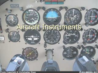
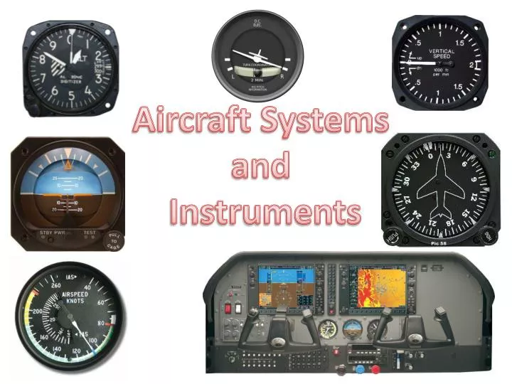
Aircraft Systems and Instruments
PTS Standards • Exhibits adequate knowledge of the elements related to applicable aircraft flight instrument system(s) and their operating characteristics to include— • Pitot-static • Altimeter • Airspeed indicator • Vertical speed indicator • Attitude indicator • Horizontal situation indicator • Magnetic compass • Turn-and-slip indicator/turn coordinator • Heading indicator • Electrical systems • Vacuum systems • Electronic flight instrument displays (PFD, MFD)
Instruments Required for Instrument Flight • DECKRAT • Directional gyro • Electrical source • Clock with seconds displayed • Kolsman-sensitive altimeter • Radios and navigation equipment, as required for the flight • Attitude indicator • Turn coordinator with inclinometer)
IFR Instruments A C K R D T E DECKRAT
VFR Day Instrument Requirements • A – airspeed indicator • T – tachometer (for each engine) • O – oil pressure gauge (for each engine using a pressure system) • M – manifold pressure gauge (for each altitude engine) • A – altimeter • T – temperature gauge (for each liquid cooled engine) • O – oil temperature gauge (for each air cooled engine) • F – fuel gauge • L – landing gear position indicator • A – anti collision lights (for aircraft certified after March 11th 1996) • M – magnetic compass • E – ELT • S – safety belts
VFR Day Instrument Requirements A2 M2 A1 F O1 & 2 A3 T1 A Tomato Flames
VFR Night Instrument Requirements • A TOMATO FLAMES plus FLAPS • F – fuses (one complete spare set) • L – landing light (only if you are flying for hire) • A – anti collision lights • P – position lights • S – source of electricity (alternator, generator)
Pitot-Static System • Pitot-static system is a system of pressure-sensitive instruments that is to determine airspeed, altitude, and vertical speed • The system includes a pitot tube, a static port, and the pitot-static instruments • Pitot tube measures ram air pressure. • Should the pitot tube and drain hole become blocked, it would probably go unnoticed in level flight. In a climb or a descent, however, ASI will behave like an altimeter because the trapped pitot pressure will be measured against varying static pressures • If only the pitot tube is blocked airspeed will decrease — possibly all the way to zero, if fully blocked • Static port - often a flush-mounted hole on the fuselage measures static pressure. • If it is blocked will lose airspeed, altitude and VSI data. Many aircraft have alternate static systems. Can also break glass on VSI to get approximate static pressure.
Pitot-Static System • Errors in pitot-static system readings can be extremely dangerous as you may lose airspeed, altitude, and vertical speed data • Several commercial airline disasters have been traced to a failure of the pitot-static system – e.g. Air France Flight 447 - crashed after its pitot tubes were blocked by ice and the crew reacted incorrectly causing a stall from which they did not recover • Altimeter, transponder and the aircraft's static system must be inspected every 24 months for IFR operations – § 91.411 • Aircraft with transponders must have encoder and transponder checked every 24 months – § 91.413
Altimeter • Altimeters compare the incoming static pressure with the pressure within its internal "aneroid wafers • As the outside static pressure decreases with altitude, the aneroid wafers expand and cause the altimeter needle to rotate around the dial • Blockage of the static source will stop the altimeter since it stops any change in pressure • Altimeter with a blocked static system will simply continue to show the same reading it had when the blockage occurred
Altimeter • The accuracy of an altimeter is subject to: • Nonstandard temperatures • Caution should be exercised when flying in proximity to obstructions or terrain in low temperatures • Nonstandard atmospheric pressure • Caution should be exercised when flying in proximity to obstructions or terrain in low pressures • Barometric pressure exceeds 31.00 inches – set altimeter to 31.00 below 18,000’ • At the beginning of the final approach segment, set the actual altimeter setting, if possible. If not, increase ceiling requirements by 100 feet and visibility requirements by 1/4 statute mile for each 1/10 of an inch of Hg above 31.00 • Pressure below 28.00 - flight by aircraft unable to set the actual altimeter setting is not recommended
Altimeter • Aircraft static port position error • Instrument error • Subject to mechanical, elastic, and temperature errors • Preflight altimeter must be within 75’ of known field elevation • An inch error in the altimeter setting equals 1,000 feet of altitude. “GOING FROM A HIGH TO A LOW or HOT TO COLD, LOOK OUT BELOW.” • GPS altitude • GPS devices read the GEOMETRIC altitude of the aircraft, relative to a sea-level baseline that is defined in the WGS84 coordinate system. This altitude is unaffected by atmospheric conditions. Aircraft Altimeters derive altitude by measuring the air pressure • At low altitudes GPS altitudes will generally agree with the barometric altimeter, subject to altimeter temperature errors • At higher altitudes, the GPS altitude and barometric altitude often diverge because of limitations of barometric altimetry
Vertical Speed Indicator • The VSI indicates the aircraft’s rate of climb or descent • The VSI uses a diaphragm connected to static pressure from the static port • The case has a calibrated nozzle that restricts the leakage of air so that there is a time delay between a change in static pressure and the pressure in the case • Thus, if the aircraft climbs (or descends), the pressure within the diaphragm will decrease (increase), while pressure in the case will decrease (increase) at a lower rate due to the presence of the nozzle • Movement of the diaphragm is translated into movement of a needle by a mechanical system
Vertical Speed Indicator • If static system is blocked, the VSI will show 0 and no change in climbs or descents • Errors • Sudden or abrupt changes in aircraft attitude cause erroneous instrument readings • While VSI needle immediately shows a change, accurate rate information is not instantaneous – can take 6 to 9 seconds • Needle should be at 0 on the ground and in level flight. This is a pre-flight check item • If not at 0, you must allow for the error when interpreting the indications in flight • If turbulence is encountered, seek to maintain an appropriate pitch attitude instead of chasing the VSI needle or trying to maintain a steady rate.
Airspeed Indicator • The input from the pitot tube is routed to a bellows in the instrument. The static input goes into the case surrounding the bellows. An increase in pitot pressure expands the bellows as long as the static pressure does not also increase, as shown in Figure 3. The expansion of the bellows rotates a gear that turns the needle on the face of the airspeed indicator and displays indicated airspeed
DECKRATAttitude Indicator 10° 20° Pointer Bank Scale 30° 45° Pitch Scale 10° 5° 90° Level / Artificial Horizon Horizon Adjustment Knob
DECKRATAutomatic Direction Indicator (ADI) Key difference is how the pointer works
Attitude indicator • Depicts the orientation of the aircraft relative to Earth's horizon • Gives immediate and direct indication of pitch and bank • A primary instrument for IFR flight • Generally vacuum powered, but can be electrically powered • Functions using the principal of rigidity in space - Aircraft rotates around the AI • Wings represent a pitch change of approximately 2° • Set wings to proper position on the ground with knob on the bottom of the instrument
Attitude indicator • Attitude indicator errors: • Can tumble if 100-110° of bank or 60-70° of pitch is exceeded • Accelerations may cause a slight pitch up indication • Deceleration may cause a slight pitch down indication • Erection can take as long as 5 minutes, but is normally done within 2 to 3 minutes • Small bank angle and pitch error possible after a 180° turn • May inaccurate display of the aircraft’s attitude, especially in skids and steep banked turns due to venting of gyro vacuum air • Can fail if vacuum or electrical power lost, as applicable • These inherent errors are small and correct themselves within a minute or so after returning to straight-and-level flight
Attitude indicator • Preflight Check: • After Engine Start • When you turn the master switch on—listen to the gyros as they spin up. Any hesitation or unusual noises should be investigated • Check the suction gauge or electrical flag indicators • Allow time for gyros to spin up. If the horizon bar erects to the horizontal position and remains at the correct position for the attitude of the airplane, or if it begins to vibrate after this attitude is reached and then slowly stops vibrating altogether, it is operating properly • Taxiing and Takeoff • Horizon bar should remain in the horizontal position during straight taxiing, and not tip in excess of 5°during taxi turns
DECKRATDirectional Gyro / Horizontal Situation Indicator (HSI) Heading bug Lubber Line 180° index – e.g, Where am I coming from Compass card adjustment knob Heading bug knob Compass card
Heading Indicator, Directional Gyro or DG • Gyro stabilized heading indicator • Indirect bank indicator (turns as heading changes) • Generally vacuum powered, but can be electrically powered • Functions using the gyroscopic principal of rigidity in space • Senses rotation about vertical axis • HI is the primary means of establishing your heading in most cases due to magnetic compass errors
Heading Indicator, Directional Gyro or DG • As a result of Earth’s rotation, and because of small errors caused by friction and imperfect balancing of the gyro, the heading indicator will drift or precess over time, and must be reset from the compass periodically • Compare the heading indicated on the HI with the compass at least every 15 minutes and reset the HI, as necessary, to match the magnetic compass in straight and level unaccelerated flight
Heading Indicator, Directional Gyro or DG • Errors • May tumble if limits are exceeded • Limits are approximately 55° of pitch and 55° of bank • Precession • During steep turns, pitching and rolling of the aircraft the changing relationship between the two gimbals in the instrument can result in a indication error or drift • Erection can take as long as 5 minutes, but normally occurs within 2 to 3 minutes • Can fail if vacuum or electrical power lost, as applicable
Heading Indicator, Directional Gyro or DG • Preflight Check: • After Engine Start • When you turn the master switch on—listen to the gyros as they spin up. Any hesitation or unusual noises should be investigated • Check the suction gauge or electrical flag indicators • Allow time for gyro to spin up and then set proper heading • Taxiing and Takeoff • HI should indicate turns in the correct direction, and precession should not be abnormal during taxi • Should match runway heading before take-off (helps to confirm you are on the correct runway!) • At idle power settings, the HI gyro may not be up to operating speeds and precession may occur more rapidly than during flight
Horizontal Situation Indicator • HSI is a combination of the Heading indicator and OBS • Many heading indicators receive a magnetic north reference from a magnetic slaving transmitter, and generally need no heading adjustment • HSI’s and HI’s that are not slaved are called "free" gyros, and require periodic adjustment • Generally same errors as HI, but can also lose magnetic slaving • Information of HSIs can be found in the VOR PowerPoint at http://bob-cfi.weebly.com/uploads/7/6/9/3/7693240/vor.pptx
Magnetic Compass • Most everything you want to know about the compass for the PTS is in my Compass turn presentation available at: http://bob-cfi.weebly.com/uploads/7/6/9/3/7693240/compass_turns.pptx
Magnetic Compass • Compass preflight checks • Fluid-filled • Moves freely • Correctly indicates known headings (taxiways, runways) – can also use a compass rose to check • Confirm deviation card is present
Turn-and-Bank Indicator • The rotor of the gyro in a turn coordinator is canted upwards 30° • Thus, it responds not only to movement about the vertical axis, but also to roll movements about the longitudinal axis • Turn coordinator thus provides an indication of roll at the earliest possible time • The airplane’s wings provide the indication of level flight and the rate at which the aircraft is turning – mark is standard rate turn • Provides no pitch information • Provides no bank information – only rate of turn Standard rate mark
Turn-and-Bank Indicator • Inclinometer • Shows the correct execution of a turn while banking the aircraft and indicates movement about the vertical axis of the aircraft (yaw) • Slip ball is completely independent of the turn coordinator • It is a round agate or steel ball, in a curved glass tube filled with dampening fluid • It moves in response to gravity and centrifugal force experienced in a turn Slip indicator
Turn-and-Bank Indicator • Turn Coordinator errors • If the air or electrical supply fails the instrument will show no turn • Usually has a warning flag • Low voltage or suction may cause the turn coordinator to show a shallower turn than actual • If gyro rotor speed is too high it will result in an excessive rate of turn indication Slip indicator
Turn-and-Bank Indicator • Preflight check • Check that the inclinometer is full of fluid and has no air bubbles • The ball should also be resting at its lowest point • When taxiing, the turn coordinator should indicate a turn in the correct direction while the ball moves opposite the direction of the turn • Check no failure flag is present Slip indicator
Electrical System • Electrical system is generally describe in Section 7 (Systems Description) of the applicable aircraft’s POH. • It is important to understand how the system works in order to troubleshoot a problem
Electrical System • Major components • Battery • Alternator – produces power to operate equipment and charge the battery • Circuit breakers – protect the system from overload • Amps / volts gauges – provide information on the status of the system • Master switch – Controls power to nearly all circuits on the aircraft • Can have two sides • Battery – powers the aircraft only from the battery • Alternator – powers the aircraft using both battery and alternator supplied power • Avionics power switch – Provides power to avionic equipment
DECKRATElectrical Source Most common electrical sources are a generator or alternator. Most modern light aircraft use alternators.
Electrical System • Potential problems • Battery failure • Alternator failure • Bus failure • Circuit breaker opens • Electrical system fire • If the system fails (non-fire) • Try to reset the alternator • Reset circuit breaker (generally only once) • Load shed non-essential equipment • If electrical fire – follow POH • Be prepared for loss of electrically powered radios and equipment • Land, as necessary following a system failure as battery power can be short lived
Vacuum System • Suction or vacuum is developed by a vacuum pump and the amount of vacuum is controlled by a vacuum relief valve / regulator located in the supply line • Pump can be engine driven or electrically driven. Some systems use a venturi arrangement to create suction. • The suction gauge monitors the vacuum developed in the system that actuates the HI and DG • The speed at which the HI and DG gyros spin needs to be within a certain range for correct operation. This speed is directly related to the suction pressure that is developed in the system and pulls a stream of air against the rotor vanes on the gyro which turns the HI or DG rotor • Similar to a water wheel
Vacuum System • Engine failure, especially on single engine aircraft, could cause a loss of vacuum and as a result cause a loss of the AI and HI at a critical time • This is why the turn and bank indicator operates with an electrically driven gyro in most cases
Electronic Flight Instrument Displays (PFD / MFD) • Digital flight displays combine all flight instruments onto a single screen which is called a primary flight display (PFD) • The traditional “six pack” of instruments is now displayed on one liquid crystal display (LCD) screen • Gyros are replaced by the Attitude Heading and Reference System (AHRS) unit • Pitot static inputs are received by an Air data computer (ADC). The ADC computes the difference between the total pressure and the static pressure, and generates the information necessary to display the airspeed on the PFD
Electronic Flight Instrument Displays (PFD / MFD) • Digital flight displays combine all flight instruments onto a single screen which is called a primary flight display (PFD) • The traditional “six pack” of instruments is now displayed on one liquid crystal display (LCD) screen • Gyros are replaced by the Attitude Heading and Reference System (AHRS) unit
Electronic Flight Instrument Displays (PFD / MFD) • A multi-function display (MFD) is usually an LCD screen surrounded by multiple buttons that can be used to display information in numerous configurable ways • MFDs often display their navigation route, moving map, weather radar, NEXRAD, GPWS, TCAS and airport information all on the same screen
Instrument Errors • Remember SRM skills – take a deep breath and think! • Remember your resources • Pitot heat • Alternate static sources • GPS altitude capabilities • Compare instruments powered from different sources vacuum gyros vs. electrical gyro (turn and bank) – gyros vs pitot/static • POH / Checklists • Keep your scan moving and identify any instrument(s) that give you conflicting information • Promptly recognizing a problem is key • Don’t ignore red flags on instruments • Identify the instrument or system that is in error by determining what makes sense and what doesn't • Develop a plan to determine which instrument has failed • Slight pitch up should tell you whether the attitude indicator is working • Bank should tell you wither the attitude indicator, turn and bank and DG are working
Instrument Errors • Remember that pitch plus power equals performance – Know your numbers • As long as you have vacuum instruments, you can keep the airplane level • Set the pitch and power for the performance you want and trust the airplane • Eliminate the erroneous instrument or system from your scan • I keep post it with me to cover an erroneous instrument to keep them from becoming distraction. Remember, your scan will tend to pick up the abnormal • With a failed instrument make very small changes and only make one change at a time and then verify that the anticipated change shows up on the instruments • DON'T become fixated on any one instrument or system • If you can't understand why an instrument is giving you a particular reading, there's a good chance there's a problem • Integrate the readings from all other instruments and determine which instrument is erroneous and eliminate it from your scan • Advise ATC of your problem as soon as you have things under control – aviate, navigate then communicate
DECKRATClock and Altimeter Must be checked every24 months
Disclaimer • Instrument flight can be dangerous. Do not rely solely on this presentation – PROFESSIONAL INSTRUCTION IS REQUIRED • The foregoing material should not be relied upon for flight • ALTHOUGH THE ABOVE INFORMATION IS FROM SOURCES BELIEVED TO BE RELIABLE SUCH INFORMATION HAS NOT BEEN VERIFIED, AND NO EXPRESS REPRESENTATION IS MADE NOR IS ANY TO BE IMPLIED AS TO THE ACCURACY THEREOF, AND IT IS SUBMITTED SUBJECT TO ERRORS, OMISSIONS, CHANGE