Download
1 / 27
270 likes | 362 Views
Sherwood Engineering. Ground Screen Replace / Compliment a Radial System. Rob Sherwood NC Ø B. We don’t all have space for a 200 x 200 foot ground system = 0.9 acres. My First House & Antenna. Purchased house in 1971 No money for a tower

E N D
Sherwood Engineering Ground Screen Replace / Compliment a Radial System Rob Sherwood NCØB We don’t all have space for a 200 x 200 foot ground system = 0.9 acres.
My First House & Antenna • Purchased house in 1971 • No money for a tower • Put up 48 foot vertical on side of house • Lot size is only 62 x 120 feet • Installed six 25 to 40-foot radials in semicircle. • Antenna barely worked & I had RF in the shack !
On 80 meters the resistive value of a 48 foot vertical with a decent ground system would be 15 to 20 ohms. • With 6 short radials the R was over 100 ohms. • Laid down a 3 x 30 foot strip of hardware mesh. • The antenna now tuned with a reasonable R value. This was my only antenna for 1 year. • Time to make some quantitative measurements.
1977 Test Setup 36 foot vertical, chicken wire ground screen, GR RF bridge, sig gen and receiver.
Measurements on a 36-Foot Vertical Data from my May 1977 hr magazine article. General Radio 916A RF Bridge Best numbers with ground screen in an X 45x2 feet + 25x5 feet at 90 degrees 200 square feet of screen 1.8 MHz Z = 8 ohms –j717. 3.6 MHz Z = 15 ohms –j279 All the data is on my web site: www.nc0b.com
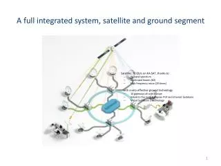
Jump ahead 30 years to new QTH • Marconi T antenna • 600+ Square Feet of Ground Screen • (Dip galvanized hardware cloth / mesh) • Screen layout in an X at 90 degrees
160 Meter T Antenna 150 or 200 foot flattop strung between two towers Could use trees or poles (If one support, flattop wires can angle down) Vertical downlead attached in the middle of flattop Vertical section is 60 feet long Redesign for 80 meters, it could be half this size. Most hams can string 75 feet of wire 30 feet in the air.
Measurements with GR RF Bridge Initial 200 foot flattop data: 1.8 MHz 36 ohms + j310 1.9 MHz 44 ohms + j363 2.0 MHz 49 ohms + j427 Now add 20 100-foot radials to see how much improvement 1.8 MHz 28 ohms + j305 1.9 MHz 36 ohms + j368 2.0 MHz 42 ohms + j438 The Z of the antenna was reduced by 8 ohms Note: 200 foot dipole lying on the ground resonant 1.9 MHz
Shortened flattop from 200 feet to 150 feet 150 foot flattop data with ground screen and 20 100 foot radials: 1.8 MHz 24 ohms +j161 (R value dropped 4 ohms) 1.9 MHz 29 ohms +j210 (R value dropped 7 ohms) 2.0 MHz 32 ohms +j262 (R value dropped 10 ohms) Now add 20 more radials for a total of 40 100 foot radials 1.8 MHz 22 ohms +j161 (R value dropped 2 more ohms) 1.9 MHz 27 ohms + j210 The radials did make up 2.0 MHz 30 ohms +j262 for shortening the flattop. The Z of the antenna decrease an additional 2 ohms Decreased the impedance of the antenna 10 ohms with 4000 feet of wire compared to just 600+ square feet of ground screen.
When is the antenna good enough? • On 160 meters I regularly worked JAs from CO with just the ground screen & 200 ft flattop. • The screen went 25 feet in 4 directions. • 100 to 650 square feet of screen have been used over the years at four different QTHs, depending on my yard size. • I picked up about 1 dB with 4000 feet of radial wire. (This value determined later.)
Tweaking the Antenna What is the optimum flattop length with a 60 foot vertical? I ran this by ON4UN who said: “The ideal length for your T would be the length where the average current in the vertical would be highest, in other words where the current maximum would be about half way up the vertical section (30 ft).” He modeled vertical wire of 60 ft and a top hat of 75 ft per side, and assuming a 5 Ohm ground loss resistance: Modeled ON4UN: 1850 kHz = 27.7 +j190 ohms (5 ohm gnd) Modeled W6XX: 1825 kHz = 27.7 +j190 ohms (20 radials) Measured: 1850 kHz = 27 +j184 ohms (screen + 20 radials)
Field Strength Measurements The pattern is almost perfectly circular on 160. Frequency Field Strength (mV/M) Theoretical 186 mV/M @ 1 mile @ 1 kW Typical @ 1.6 MHz 165 mV/M, good soil (-1.0 dB) KRXY @ 1.6 MHz 160 mV/M (-1.3 dB) NC0B @ 1.9 MHz 130 mV/M (-3.1 dB) W7KKD @ 1.8 MHz 110 mV/M * (-4.6 dB) * (50-foot vertical, 20-foot top loading hat & 12 radials)
Efficiency with 150 foot flattop @ 1 Mile 40 Radials + Ground Screen Z = 27 ohms Theoretical Measured Difference 186 mV/M 130 mV/M (-3.1 dB) @ 400 & 800 feet NEC implies ground losses 7 ohms 20 Radials + Ground Screen Z = 29 ohms Extrapolate 125 mV/M (-3.5 dB) Increase ground losses to 9 ohms Adding 20 radials improved signal 0.4 dB
Calculated watts in vertical section 150 foot & 40 radials + screen 741 W Reference 150 foot & 20 radials + screen 690 W -0.31 dB 200 foot & 20 radials + screen 750 W +0.05 dB 200 foot & screen only 614 W -0.87 dB 10 Log Power1/Power2 = dB If you don’t have an acre of ground and almost a mile of wire, you can compete by using just a ground screen and a reasonable size top-loaded vertical.
Reality Check – Are Numbers reasonable? • Paper from NAB 1996, Kintronic Labs, Inc. measurements at Bluff City, TN. • 0.27* wave tower, 120 radials, 1680 kHz, Ref • Ground stake only, signal level -2.7 dB • 0.17^ wave tower, 120 radials, -1.4 dB • Ground stake only, signal level -5.2 dB • * 150 feet • ^ 95 feet
Radiation Pattern courtesy W6XX 160 meter peak radiation near 30 degrees. 1 dB down at 15 degrees above the horizon. Note: Not a cloud warmer, down 10 dB at 75 degrees above the horizon.
Horizontal dipole @ 1/8th wave length Horizontal is efficient. Favors short skip, making DX weaker by comparison to state-side QRM. 10 dB down at 15 degrees.
Radiation Pattern 160 Meters by W6XX Red = Horizontal Down 29 dB or more from the vertical radiation pattern.
How does it work on 80 meters? Red = Horizontal Down 10 dB or more from the vertical radiation pattern. If the antenna is scaled to 80 meters, then it is a perfectly good antenna on 80 & 40 meters.
Field Strength on 80 Meters • Voltage fed: 2400 ohms + j4000 ! • Field Strength @ 1 mile & 1 kW • 80 mV/meter in line with flattop • 45 mV/meter 90 degrees to flattop • More groundwave loss on 80 vs. 160 meters.
Summary • What’s practical for your QTH? • Ground screen better than a few radials. • Broadcasters use a screen + radials. • Limited space? Use a ground screen. • How much? Shoot for 400 square feet. • Don’t recommend less than 100 sq ft. • Add radials? 16 or more, or don’t bother. • 4 radials do virtually nothing.
Sherwood Engineering http://www.NC0B.com Thanks to W6XX and K0ELM for their invaluable assistance