Download
1 / 18
390 likes | 994 Views
Space Shuttle Launch System and Failures. External Tank (ET). Space Shuttle consists of: Reusable orbiter with a large 15 ft diameter by 60 ft long cargo bay for payloads. Expendable external tank supplies fuel to the 3 orbiter engines.

E N D
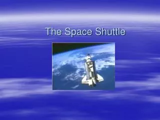
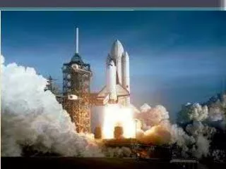
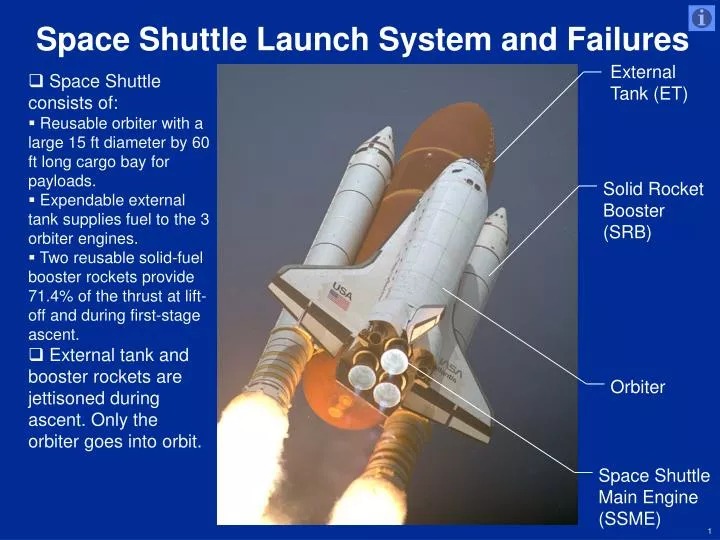
Space Shuttle Launch System and Failures External Tank (ET) • Space Shuttle consists of: • Reusable orbiter with a large 15 ft diameter by 60 ft long cargo bay for payloads. • Expendable external tank supplies fuel to the 3 orbiter engines. • Two reusable solid-fuel booster rockets provide 71.4% of the thrust at lift-off and during first-stage ascent. • External tank and booster rockets are jettisoned during ascent. Only the orbiter goes into orbit. Solid Rocket Booster (SRB) (SRB) Orbiter Space Shuttle Main Engine (SSME) http://grin.hq.nasa.gov/IMAGES/LARGE/GPN-2000-000736.jpg
Solid Rocket Booster Nose Cap • Each SRB consists of: • Nose cap and frustum include the pilot, drogue and 3 main parachutes. • Forward skirt contains avionics, range safety system and ET attach fitting. • Four solid rocket motor segments with propellant. • Aft attach ring includes provisions for ET attachment. • Aft skirt bolts the SRB to the launch pad prior to lift-off. • Nozzle is gimbaled for control. • Orbiter SSMEs are ignited while SRBs are bolted to the launch pad. • Thrust bends the shuttle assembly creating loads. • SRBs are ignited after the thrust level of the SSMEs is verified. • SRBs separate from the launch pad and shuttle assembly springs back creating “twang” motion. Frustum Forward Skirt Forward ET Attach Ring Forward Field Joint Center Field Joint Aft ET Attach Ring and Aft Field Joint Aft Skirt Launch Pad Separation Motors (4 Places) Nozzle http://spaceflight.nasa.gov/gallery/images/shuttle/sts-114/hires/sts114-s-041.jpg
Solid Rocket Booster – Challenger Accident • STS-51L, Challenger, January 28, 1986 • Gray smoke comes from the right SRB aft field joint 0.68 seconds after ignition. • Challenger explodes 73 seconds into the flight. • The cause of the accident was cold weather and the right SRB aft field joint sealing, shown below. • The SRB aft field joint sealing is redesigned as a result of the accident. PrimaryO-ring Segment Tang Leak Check Port O-ring Grease Bead Insulation Shim Clevis Pin Propellant Filled Insulation Gap Cork Insulation Gray Smoke Putty Segment Clevis Insulation http://history.nasa.gov/rogersrep/v6p14.htm http://grin.hq.nasa.gov/IMAGES/LARGE/GPN-2000-001347.jpg
Space Shuttle Main Engines • Liquid oxygen (LOX) oxidizer at -298 OF from the External Tank enters the orbiter at the umbilical disconnect and flows to the orbiter's LOX feed line. There it branches into three parallel paths, one to each engine. • Liquid hydrogen fuel at -423 OF from the External Tank flows into the orbiter at the liquid hydrogen feed line disconnect valve. It then enters the orbiter hydrogen feed line manifold and branches out into three parallel paths to each engine. Space Shuttle Main Engines External Tank LOX Feed Line Flight Deck Mid Deck http://www.jlhs.nhusd.k12.ca.us/Classes/Social_Science/Challenger.html/Challenger.html
External Tank • The 27.5 ft diameter by 154 ft long ET is the largest single piece of the Space Shuttle. • During launch the ET acts as the backbone supporting the orbiter and SRBs. • The ET holds the liquid hydrogen fuel and liquid oxygen oxidizer for the orbiter’s three engines in separate pressurized tanks. Propellant Feed, Pressurization Lines and Electrical Umbilicals Liquid Oxygen Feedline Orbiter Aft Attachment Orbiter Forward Attachment Not Shown Liquid Hydrogen Tank Solid Rocket Booster (SRB) Forward Attachment Intertank Liquid Oxygen (LOX) Tank http://www.nasa.gov/centers/marshall/multimedia/photogallery/photos/photogallery/shuttle//shuttle.html
External Tank Debris – Columbia Accident STS-107, Columbia, February 1, 2003 • Falling foam, the size of a suitcase, from the orbiter forward attachment opened a hole in Columbia’s left wing, leading to the orbiter's breakup on entry. • The forward attachment, shown top right, used a foam ramp to prevent ice on the fitting. • The new design, shown below, uses heaters instead of foam to prevent ice buildup. Orbiter Forward Attachment http://spaceflight.nasa.gov/gallery/images/shuttle/sts-110/hires/sts110-337-001.jpg
http://spaceflight.nasa.gov/gallery/images/shuttle/sts-114/hires/jsc2005e30569.jpghttp://spaceflight.nasa.gov/gallery/images/shuttle/sts-114/hires/jsc2005e30569.jpg External Tank Debris - Discovery STS-114, Discovery, July 26, 2005 • Large piece of ET foam separated from an area of the tank called the the Protuberance Air Load (PAL) ramp near the liquid oxygen feed line. • Debris did not impact Discovery but the Shuttle fleet was grounded. • NASA currently plans to replace the PAL ramps with an enhanced manual foam spraying process. • In November 2005, NASA investigators found 9 cracks in the PAL on the ET originally slated for the STS-114 mission. http://www.nasa.gov/returntoflight/multimedia/external_tank_images.html
Reference Information END The Space Shuttle Operator’s Manual, Kerry Mark Joels, Random House, 1982 Report of the Presidential Commission on the Space Shuttle Challenger Accident, William Rogers, U.S. Government, 1986 Columbia Accident Investigation Board, U.S. Government, 2003 Foam Puzzle, Aviation Week & Space Technology, November 28, 2005 Images and Text: http://grin.hq.nasa.gov/ http://spaceflight.nasa.gov/ http://history.nasa.gov/rogersrep/v6p14.htm http://www.jlhs.nhusd.k12.ca.us/Classes/Social_Science/Challenger.html/Challenger.html http://www.nasa.gov/centers/marshall/multimedia/photogallery/photos/photogallery/shuttle//shuttle.html http://www.nasa.gov/returntoflight/multimedia/external_tank_images.html Text only: http://science.ksc.nasa.gov/shuttle/technology/sts-newsref/srb.html http://science.ksc.nasa.gov/shuttle/missions/51-l/mission-51-l.html http://science.ksc.nasa.gov/shuttle/technology/sts-newsref/sts-mps.html#sts-mps-ssme http://www.braeunig.us/space/propel.htm http://www.nasa.gov/centers/marshall/multimedia/photogallery/photos/photogallery/shuttle//shuttle.html http://www.space.com/missionlaunches/ft_051001_et_fixes.html
Space Shuttle Statistics • Length • Space Shuttle: 184.2 feet • Orbiter: 122.2 feet • Height • Orbiter on runway: 56.7 feet • Wingspan: • 78.1 feet • Weight* • At liftoff: 4.5 million pounds • End of mission: 230,000 pounds • Maximum cargo to orbit: • 63,500 pounds • SRB Separation: • 2 minutes after launch • External Tank Separation: • 8.5 minutes after launch • Altitude: 69 miles • Velocity: 17,440 miles/hour • Orbit: • 115 to 400 miles • Velocity: 17,321 miles/hour * Weight dependent on payloads and on-board consumables.
Solid Rocket Booster • The SRBs, 12.2 ft in diameter by 149.2 ft long, are the largest solid-propellant motors flown and the first designed for reuse. • Each SRB weighs about 1,300,000 pounds at launch. The propellant for each solid rocket motor weighs about 1,100,000 pounds. • 2 SRBs carry the entire weight of the ET and orbiter and transmit the weight load through their structure to the launch pad. • Each booster is attached to the mobile launcher platform at the aft skirt by four bolts and nuts that are severed by small explosives at lift-off. • 2 SRBs provide the main thrust to lift the space shuttle off the pad to an altitude of about 28 miles. • Each booster has a thrust at sea level of about 3,300,000 pounds at launch. They are ignited after the thrust level of the three space shuttle main engines is verified. • 75 seconds after SRB separation, SRB apogee occurs at an altitude of about 41 miles with SRB impact in the ocean about 141 miles downrange. • Primary elements of each booster are the motor (including steel case, propellant, igniter and nozzle), separation systems, operational flight instrumentation, recovery avionics, pyrotechnics, deceleration system, thrust vector control system and range safety destruct system. • Each booster is attached to the ET at the SRB's aft frame by two lateral sway braces and a diagonal attachment. The forward end of each SRB is attached to the ET at the end of the SRB's forward skirt.
Challenger Accident Timeline • 6.6 seconds before launch - Challenger's three main engines are ignited and run up to full thrust while the Shuttle structure is bolted to the launch pad. The thrust of the main engines bends the Shuttle assembly forward from the bolts anchoring it to the pad. When the Shuttle assembly springs back to the vertical, the SRBs' restraining bolts are explosively released. During this pre-release "twang" motion, structural loads are stored in the assembled structure. These loads are released during the first few seconds of flight. The maximum structural loads on the SRBs’ aft field joints occurs during the "twang.“ • 0.68 seconds after lift-off - strong puff of gray smoke spurted from the vicinity of the right SRB aft field joint facing the ET. • 2.73 seconds - vaporized material streaming from the joint indicated the field joint was not sealed. The black color and dense composition of the smoke puffs suggest the grease, joint insulation and rubber O-rings in the joint seal were being burned and eroded by the 5000 0F propellant gases. • 64.66 seconds - swirling flame from the SRB breached the ET indicating the flame was mixing with leaking hydrogen from the ET. Within 45 milliseconds of the breach, a bright, sustained glow developed on the black-tiled underside of Challenger. • 72 seconds - Challenger struggled futilely against the forces that were destroying the orbiter.
Challenger Accident Timeline (Continued) • 72.20 seconds - the lower strut linking the SRB and the ET was severed or pulled away from the weakened hydrogen tank permitting the right SRB to rotate around the upper attachment strut. • 73.12 seconds - a circumferential white vapor pattern bloomed from the side of the ET bottom dome beginning the structural failure of the hydrogen tank. The failure culminated in the entire aft dome dropping away, releasing massive amounts of liquid hydrogen from the tank. This created a sudden forward thrust pushing the hydrogen tank upward into the ET intertank structure. At about the same time, the rotating right SRB impacted the intertank structure and the lower part of the liquid oxygen tank. • 73.14 seconds – The intertank structure and liquid oxygen tank fail. Within milliseconds there is a massive, almost explosive, burning of the hydrogen streaming from the failed tank bottom and liquid oxygen breach in the area of the intertank. Challenger was totally enveloped in the explosive burn at this point in its trajectory traveling at a Mach number of 1.92 at an altitude of 46,000 ft. The Challenger's reaction control system ruptured and a hypergolic burn of its propellants occurred as it exited the oxygen-hydrogen flames. The orbiter, under severe aerodynamic loads, broke into several large sections which emerged from the fireball. Separate sections included the main engine/tail section with the engines still burning, one wing of the orbiter, and the forward fuselage trailing a mass of umbilical lines pulled loose from the payload bay. • The explosion, 73 seconds after liftoff, claimed crew and vehicle.
Main Engine Statistics:Thrust Sea level: 375,000 poundsVacuum: 470,000 poundsNominal operating time8.5 minutes after liftoffLife 7.5 hours, 55 starts • After the SRBs are jettisoned, the main engines provide thrust accelerating the Shuttle from 3,000 mph to over 17,000 mph in just six minutes to reach orbit. • The 3 engines create a combined maximum thrust of more than 1.2 million pounds. • Engine exhaust is primarily water vapor as the hydrogen and oxygen combine. • As the engines push the Shuttle toward orbit, they consume liquid fuel at a rate draining an average family swimming pool in under 25 seconds generating over 37 million horsepower. • Engines can be throttled over a thrust range of 65% to 109%. • The range provides for a high thrust level during liftoff and the initial ascent phase but allows thrust to be reduced to limit acceleration to 3 g's during the final ascent phase. • The engines are gimbaled to provide pitch, yaw and roll control during the ascent. Space Shuttle Main Engines Propellant Mixture (by weight) 6 parts liquid oxygen to 1 part liquid hydrogen Weight Approximately 6,700 pounds each Dimensions 14 ft long 7.5 ft wide at mouth of nozzle
External Tank • The three main components of the ET are a liquid oxygen tank, located in the forward position, an aft-positioned liquid hydrogen tank, and a collar-like intertank. • Intertank connects the two propellant tanks, houses instrumentation and processing equipment, and provides the attachment structure for the forward end of the SRBs. • ET is attached to the orbiter at one forward attachment point and two aft points. • Umbilicals that carry fluids, gases, electrical signals and electrical power between the ET and the orbiter are located at the aft attachment. • Electrical signals and controls between the orbiter and the two SRBs are routed through the umbilicals. • ET includes a propellant feed system to duct the propellants to the orbiter engines, a pressurization and vent system to regulate the tank pressure, an environmental conditioning system to regulate the temperature and render the atmosphere in the intertank area inert, and an electrical system to distribute power and instrumentation signals and provide lightning protection. • ET propellants are fed to the orbiter through a 17 inch diameter connection that branches inside the orbiter to feed each main engine. • ET skin is covered with a Thermal Protection System (TPS) that is a 1 inch thick coating of spray-on foam. The purpose of the TPS is to maintain the propellants at an acceptable temperature, to protect the skin surface from aerodynamic heat, and to minimize ice formation.
Columbia Accident • Physical cause of the loss of Columbia and its crew was a breach in the Thermal Protection System (TPS) on the leading edge of the left wing. • A piece of insulating foam separated from the left bipod ramp section of the ET 81.7 seconds after launch, and struck the wing in the vicinity of the lower half of Reinforced Carbon-Carbon panel number 8. • During re-entry this breach in the TPS allowed superheated air to penetrate through the leading edge insulation and progressively melt the aluminum structure of the left wing, weakening the structure. • Increasing aerodynamic forces caused loss of control, failure of the wing, and break-up of the orbiter. • Breakup occurred in a flight regime where there was no possibility for the crew to survive.
Discovery ET Debris • PAL ramp runs along the side of the ET ensuring smooth airflow and minimizing vibration around nearby pipes and cables. • Three fixes are being considered for the PAL ramps: • Current plan - replace all PAL ramps with an enhanced manual foam spraying process. • Possibility for future use - a robotic spraying system is being tested, similar to the system that sprays foam on the ET. • Under study - PAL ramps will be removed if aerodynamic studies show they are no longer needed. • 9 cracks were found in the hydrogen tank PAL ramp of the ET that was replaced for STS-114. • Inspection of an ET that had been stacked on the launch pad and filled with cryogenic propellants and pressurized is rare. • Cracks in the PAL ramp were not found in another ET that was not filled with cryogenic propellants and not pressurized. • Cryogenic temperatures shrink the tank, causing stress on the foam, and alter its strength as well. • Tests will determine if the cracks are significant or can be ignored. • Shuttle fleet remains grounded while NASA determines how to stop big pieces of foam insulation from breaking off the tanks during liftoff.