1 / 36

E N D
8085 MICROPROCESSOR ARCHITECTURE Mrs.Mahalakshmi.V Assistant Professor – ECE Vel Tech Rangarajan Dr.Sagunthala R&D Institute of Science and Technology.
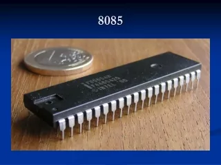
Features of 8085 Microprocessor • 8 bit general purpose microprocessor. • It has 40 pins (dip) dual in line package. • Capable of addressing 64K of memory. • It requires+5V power supply. • It can operate with 3Mhz clock. • It provides 74 instructions. • It has on chip clock generator. • 8-bit data bus. • 16-bit address bus, which can address up to 64KB. • Six 8-bit registers arranged in pairs: BC, DE, HL • A 16-bit program counter, stack pointer.
Intel 8085 Microprocessor Microprocessor consists of: • Control unit: control microprocessor operations. • ALU: performs data processing function. • Registers: provide storage internal to CPU. • Interrupts • Internal data bus, Address bus
Register sets of 8085 • General Purpose Registers • B, C, D, E, H & L (8 bit register) • Can be used singly or can be used as 16 bit register pairs BC, DE, HL. • H & L can be used as a data pointer (holds memory address) • Special Purpose Registers • Accumulator (8 bit register)
Accumulator: • It is a 8-bit register which is used to perform arithmetical and logical operation. • It stores the output of any operation. • It also works as registers for i/o accesses. Temporary Register • It is a 8-bit register which is used to hold the data on which the accumulator is computing operation. • It is also called as operand register because it provides operands to ALU. Stack pointer • It is also a 16-bit register works like stack, which is always incremented/decremented by 2 during push & pop operations.
Program counter • It is a 16-bit register used to store the memory address location of the next instruction to be executed. • Microprocessor increments the program whenever an instruction is being executed. • The program counter points to the memory address of the next instruction that is going to be executed. Flag register Sign (S) Zero (Z) Auxiliary Carry (AC) Parity (P) Carry (C)
Instruction register and decoder • It is an 8-bit register. • When an instruction is fetched from memory then it is stored in the Instruction register. • Instruction decoder decodes the information present in the Instruction register. • Timing and control unit • It provides timing and control signal to the microprocessor to perform operations. • Following are the timing and control signals, which control external and internal circuits − • Control Signals: READY, RD’, WR’, ALE • Status Signals: S0, S1, IO/M’ • DMA Signals: HOLD, HLDA • RESET Signals: RESET IN, RESET OUT
Control signals of 8085 • Arithmetic Latch Enable (ALE) It is an output signal used to give information of AD0-AD7 contents. High – Address, Low - Data 2.Read (RD) signal This is active low used for reading operation. 3.Write signal (WR) This is active low used for writing operation. Interrupt signals of 8085 Interrupts are the signals generated by external devices to request the microprocessor to perform a task. There are 5 interrupt signals, i.e. TRAP, RST 7.5, RST 6.5, RST 5.5, and INTR.
8085 Pin Diagram- Explanation • Address bus (Pin no:21-28) • A15-A8, it carries the most significant 8-bits of memory/IO address. • Data bus (Pin no:12-19) • AD7-AD0, it carries the least significant 8-bit address and data bus. • Power supply(Pin no: 20&40) • There are 2 power supply signals − VCC & VSS. VCC indicates +5v power supply and VSS indicates ground signal.
8085 Pin Diagram- Explanation 3 clock signals • X1, X2(Pin no:1&2) • A crystal (RC, LC N/W) is connected at these two pins and is used to set frequency of the internal clock generator. This frequency is internally divided by 2. • CLK OUT(Pin no:37) • This signal is used as the system clock for devices connected with the microprocessor
8085 Pin Diagram- Explanation Status signals So,S1,IO/M* (Pin no: 29.33&34)
8085 Pin Diagram- Explanation 3 Control signals RD*, WR* & ALE (Pin no: 31,32&30) • RD* • This signal indicates that the selected IO or memory device is to be read and is ready for accepting data available on the data bus. • WR* • This signal indicates that the data on the data bus is to be written into a selected memory or IO location. • ALE(Address Latch Enable) • It is a positive going pulse generated when a new operation is started by the microprocessor. • When the pulse goes high, it indicates address. • When the pulse goes down it indicates data.
8085 Pin Diagram- Explanation Interrupts and INTA signals • Interrupts (Pin no: 6-10) • Interrupts are the signals generated by external devices to request the microprocessor to perform a task. • There are 5 interrupt signals, i.e. TRAP, RST 7.5, RST 6.5, RST 5.5, and INTR. • INTA(Interrupt Acknowledge) (Pin no:11) • When the 8085 microprocessor gets an interrupt signal, then it should be recognized. • When the interrupt will be obtained then INTA will go high.
8085 Pin Diagram- Explanation Externally Initiated Signals RESET IN(Pin no: 36)− This signal is used to reset the microprocessor by setting the program counter to zero. RESET OUT (Pin no: 3) − This signal is used to reset all the connected devices when the microprocessor is reset. READY (Pin no: 35) − This signal indicates that the device is ready to send or receive data. If READY is low, then the CPU has to wait for READY to go high. HOLD (Pin no: 39) − This signal indicates that another master is requesting the use of the address and data buses. HLDA (HOLD Acknowledge) (Pin no: 38) − It indicates that the CPU has received the HOLD request and it will relinquish the bus in the next clock cycle. HLDA is set to low after the HOLD signal is removed.
8085 Pin Diagram- Explanation Serial I/O signals • SOD (Pin no:4) • Serial output data line • The output SOD is set/reset as specified by the SIM instruction. • SID (Pin no:5) • Serial input data line • The data on this line is loaded into accumulator whenever a RIM instruction is executed.
Timing Diagram • Timing Diagram • It is a graphical representation. • It represents the execution time taken by each instruction in a graphical format. • The execution time is represented in T-states. • Instruction Cycle: • The time required to execute an instruction is called instruction cycle. • Machine Cycle: • The time required to access the memory or input/output devices is called machine cycle. • T-State: • The machine cycle and instruction cycle takes multiple clock periods. • A portion of an operation carried out in one system clock period is called as T-state.
MACHINE CYCLES OF 8085 • The 8085 microprocessor has 5 (seven) basic machine cycles. They are • Opcode fetch cycle (4T) • Memory read cycle (3 T) • Memory write cycle (3 T) • I/O read cycle (3 T) • I/O write cycle (3 T)
The following signals are required: • AD0-AD7 • A8-A15 • ALE • 1-Address • 0- Data • IO/M* • 1-IO • 0- Memory • SO&S1 MVI A, 03H OPCODE FETCH 2000: 3EH 2001: 03H RD* MP Memory Address Bus
Timing diagram of MVI instruction Problem – Draw the timing diagram of the following code, MVI B, 45 Explanation of the command – It stores the immediate 8 bit data to a register or memory location. Example: MVI B, 45Opcode: MVIOperand: B is the destination register and 45 is the source data which needs to be transferred to the register.’45’ data will be stored in the B register.
Algorithm – • Decide what is the opcode and what is the data. Here, opcode is ‘MVI B’ and data is 45. • Assume the memory address of the opcode and the data. For example MVI B, 452000: Opcode2001: 45 • The opcode fetch will be same in all the instructions. • Only the read instruction of the opcode needs to be added in the successive T states. • For the opcode fetch the IO/M (low active) = 0, S1 = 1 and S0 = 1. Also, 4 T states will be required to fetch the opcode from memory. • For the opcode read the IO/M (low active) = 0, S1 = 1 and S0 = 0. Also, only 3 T states will be required to read data from memory.
In Opcode fetch ( t1-t4 T states ) – • 00 – lower bit of address where opcode is stored. • 20 – higher bit of address where opcode is stored. • ALE – Provides signal for multiplexed address and data bus. Only in t1 it used as address bus to fetch lower bit of address otherwise it will be used as data bus. • RD (low active) – Signal is 1 in t1 & t4, no data is read by microprocessor. Signal is 0 in t2 & t3, data is read by microprocessor. • WR (low active) – Signal is 1 throughout, no data is written by microprocessor. • IO/M (low active) – Signal is 0 in throughout, operation is performing on memory. • S0 and S1 – Signal is 1 in t1 to t4 states, as to fetch the opcode from the memory.
In Opcode read ( t5-t7 T states ) – • 01 – lower bit of address where data is stored. • 20 – higher bit of address where data is stored. • ALE – Provides signal for multiplexed address and data bus. Only in t5 it used as address bus to fetch lower bit of address otherwise it will be used as data bus. • RD (low active) – Signal is 1 in t5 as no data is read by microprocessor. Signal is 0 in t6 & t7 as data is read by microprocessor. • WR (low active) – Signal is 1 throughout, no data is written by microprocessor. • IO/M (low active) – Signal is 0 in throughout, operation is performing on memory. • S0 – Signal is 0 in throughout, operation is performing on memory to read data 45. • S1 – Signal is 1 throughout, operation is performing on memory to read data 45.
Instruction Format Destination operand • A Machine code instruction consists of operation code(opcode) and operand. • Opcode is the task to be performed. • Operand is the data to be operated. Example MVI A, 45H Example EX: INC A Source operand • The Instruction Format of 8085 set consists of one, two and three byte instructions.
Some Important Terminology to understand Microprocessor What is Microprocessor? Why binary digits are used in microprocessor? Why hexa decimal is preferred rather than other number system? What is bus and list the types of buses? How microprocessor performs a task? What is clock signal and why it is required in mp? What is program? What is Assembly language? What is Machine language? What is register? What is memory? What is an instruction?