Download
1 / 40
490 likes | 1.44k Views
Analysis of the Coupled Journal and Thrust Bearing. August 21 2004 Hakwoon Kim PREM, Department of Mechanical Engineering Hanyang University, Seoul, Korea. Contents. Motivation Reynolds Equation - Reynolds equation - Boundary condition - Load capacity and friction torque

E N D
Analysis of the CoupledJournal and Thrust Bearing August 21 2004 Hakwoon Kim PREM, Department of Mechanical Engineering Hanyang University, Seoul, Korea
Contents • Motivation • Reynolds Equation - Reynolds equation - Boundary condition - Load capacity and friction torque - Finite element method for a coupled journal and thrust bearing • Perturbation - Physical perturbation • Analysis Result - Coupled analysis vs separate analysis of FDB of a 3.5 " HDD - Reynolds BC vs half-Sommerfeld BC of FDB of a 3.5 " HDD - FDB of a 1" Micro Driver with the effect of recirculation channel - Result and discussion • Future Work
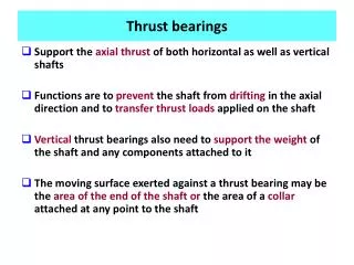
Thrustbearings Journalbearings Journalbearings Plainareas Plainareas Thrustbearings Plainareas Motivation < Structure of a 3.5" FDB spindle motor > < Structure of a 1" FDB spindle motor > • FDB of HDDs is composed of several sections, which are grooved or plain journal or thrust bearings. • Sometimes, they are connected through recirculation channel. • One section affects the others in terms of pressure and flow of lubricant
y q h e C 1 C 2 z x F Journal L/2 0 Sleeve 2 -L/2 Line of Centers Reynolds equation • Reynolds equation for journal bearing - filmthickness : < Journal bearing geometry >
z = h h ( r , ) r r Thrust Thrust Pad Reynolds equation • Reynolds equation for thrust bearing - filmthickness : < Thrust bearing geometry >
p p p q q q * < Reynolds BC > < Full Sommerfeld BC > < Half Sommerfeld BC > C 1 y C 2 q Journal e Sleeve x F Line of Centers Boundary condition • The solution for a full 360 degree journal bearing leads to skew-symmetric pressure distribution. • The pressures in the divergent film are all lower than ambient pressure. • The negative pressure can be neglected with the fact that the saturation pressure is similar to ambient pressure • But it violates the continuity of mass flow and pressure gradient at the outlet end of the pressure curve. • The better boundary condition is Reynolds BC, where • * can be determined numerically by the iterative method.
Load capacity and friction torque • Use the finite element method to solve Reynolds equation and to determine the pressure distribution • Load capacity, friction torque and attitude angle of journal bearing • Load capacity, friction torque of thrust bearing
Part 1 Part 2 Part 3 External ambient pressure Interface Periodic boundary Finite element method for a coupled journal and thrust bearing • Calculate the finite element matrix for journal and thrust bearing appropriately • Assemble the element matrix to global matrix • Apply the BC at the external boundaries • At the internal boundaries, pressure and mass continuity is automatically conserved • In case of Reynolds BC, the global finite element equation is iteratively solved until Reynolds BC is satisfied
Perturbation • In the case of coupled journal and thrust bearing, the boundary value problem can not be defined because the perturbed pressure on the interface between the journal and the thrust bearing is not defined • Physical perturbation has to be used for this case • Dynamic coefficients are calculated by comparing the change of bearing reaction forces and moments with respect to the change of translational and angular displacements and velocities in each direction
Perturbation 3.1 Perturbation for journal bearing • Step 1 : Set the coordinate system considering attitude angle calculated by initial static analysis • Step 2 : Calculate the initial load and moment with respect to the new coordinate system • Step 3 : Calculate the loads and moments considering perturbed displacements and velocities, i.e. • Step 4 : Calculate the dynamic characteristics from following equation < Geometrical description of physical perturbation by ex >
Fz2 Thrust Fz1 Thrust pad Perturbation 3.2 Perturbation for thrust bearing • Step 1 : Set the coordinate system • Step 2 : Calculate the initial load and moment with respect to the fixed coordinate system • Step 3 : Calculate the loads and moments considering perturbed displacements and velocities, i.e. • Step 4 : Calculate the dynamic characteristics < Geometrical description of physical perturbation by ez >
Perturbation • Merits of physical perturbation • It is not necessary to consider boundary values of perturbation equations • It can handle any case of hydrodynamic bearing including the coupled journal and thrust bearing • The radial-and-axial coupled stiffness and damping can be observed • Demerits of physical perturbation • This method is dependent on the amount of perturbation, i.e., perturbed displacement and velocity • It needs fine mesh for a good estimate • It takes longer computational time than mathematical perturbation method
(1) (2) (3) (4) (6) (5) (7) (9) (8) Analysis result 4.1 Coupled analysis vs. separate analysis of FDB of a 3.5 " HDD
Analysis result • Specification of analysis model
< Pressure distribution> < Mesh for finite element method > Analysis result • Analysis model and result of pressure distribution • Number of node = 6121 [EA] • Number of element = 5508 [EA] • Element type : 4-node quadrilateral element
Analysis result • Result comparison between coupled analysis and separate analysis • Pressure distribution • Eccentricity ratio = 0.1 • Max pressure in upper journal = 3.344 [MPas] • Max pressure in lower journal = 3.314 [MPas] • Eccentricity ratio = 0.1 • Max pressure in upper journal = 3.124 [MPas] • Max pressure in lower journal = 2.934 [MPas] < Coupled analysis of journal bearing > < Separate analysis of journal bearing >
Analysis result • Clearance = 9.0 [㎛] • Max pressure in upper journal = 509.1 [KPas] • Clearance = 9.0 [㎛] • Max pressure in upper journal = 110.2 [KPas] < Coupled analysis of upper thrust bearing > < Separate analysis of upper thrust bearing >
Analysis result • Clearance of lower thrust = 9.0 [㎛] • Clearance of center plain = 500 [㎛] • Max pressure in upper journal = 529.8 [KPas] • Clearance = 9.0 [㎛] • Max pressure in upper journal = 125.3 [KPas] < Coupled analysis of lower thrust bearing > < Separate analysis of lower thrust bearing >
Analysis result • Static characteristics
Analysis result • Dynamic characteristics • Stiffness coefficient comparison • Damping coefficient comparison
(1) (2) (3) (4) (6) (5) (7) (9) (8) Analysis result 4.2. Reynolds BC vs half-Sommerfeld BC of FDB of a 3.5 " HDD
Analysis result • Specification of analysis model
< Mesh for finite element method > Analysis result • Number of node = 6121 [EA] • Number of element = 5508 [EA] • Element type : 4-node quadrilateral element
Analysis result • Result comparison between using half Sommerfeld BC and Reynolds BC • Pressure distribution • Max pressure in FDB = 2.984 [MPas] • Max pressure in FDB = 3.036 [MPas] < Analysis result using half Sommerfeld BC > < Analysis result using Reynolds BC >
Analysis result • Eccentricity ratio = 0.1 • Max pressure in upper journal = 2.984 [MPas] • Max pressure in lower journal = 2.971 [MPas] • Eccentricity ratio = 0.1 • Max pressure in upper journal = 3.036 [MPas] • Max pressure in lower journal = 3.105 [MPas] < Analysis result using half Sommerfeld BC > < Analysis result using Reynolds BC >
Analysis result • Clearance of lower thrust = 9.0 [㎛] • Max pressure in upper journal = 39.467 [KPas] • Clearance = 9.0 [㎛] • Max pressure in upper journal = 212.350 [KPas] < Analysis result using half Sommerfeld BC > < Analysis result using Reynolds BC >
Analysis result • Clearance of lower thrust = 9.0 [㎛] • Clearance of center plain = 500 [㎛] • Max pressure in upper journal = 38.969 [KPas] • Clearance = 9.0 [㎛] • Clearance of center plain = 500 [㎛] • Max pressure in upper journal = 213.540 [KPas] < Analysis result using half Sommerfeld BC > < Analysis result using Reynolds BC >
Analysis result • Static characteristics
Analysis result • Dynamic characteristics • Stiffness coefficient comparison • Damping coefficient comparison
(1) (8) (2) (3) (4) (5) (9) Analysis result 4.3. FDB of a 1" Micro Driver with the effect of recirculation channel - 3 recirculation channels between upper thrust bearing and lower plain thrust bearing
Analysis result • Specification of analysis model
< Pressure distribution in FDB> < Mesh for finite element method > Analysis result • Analysis model and result of pressure distribution • Number of node = 11041 [EA] • Number of element = 10000 [EA] • Element type : 4-node quadrilateral element
Analysis result • Result comparison between FDB with recirculation channel and FDB without recirculation channel • Pressure distribution • Eccentricity ratio = 0.1 • Max pressure in upper journal = 302.960 [KPas] • Max pressure in lower journal = 297.770 [KPas] • Eccentricity ratio = 0.1 • Max pressure in upper journal = 292.080 [KPas] • Max pressure in lower journal = 269.470 [KPas] < Journal bearing without recirculation channel> < Journal bearing with recirculation channel>
Analysis result • Clearance = 15.0 [㎛] • Max pressure in thrust= 208.64 [KPas] • Clearance = 15.0 [㎛] • Max pressure in thrust = 209.03 [KPas] < Thrust bearing without recirculation channel> < Thrust bearing with recirculation channel>
Analysis result • Clearance = 500.0 [㎛] • Max pressure in lower plain = 56.634 [KPas] • Clearance = 500.0 [㎛] • Max pressure in lower plain = 19.636 [KPas] < Lower plain bearing without recirculation channel> < Lower plain bearing with recirculation channel>
Analysis result • Clearance = 500.0 [㎛] • Max pressure in lower plain = 56.634 [KPas] • Clearance = 500.0 [㎛] • Max pressure in lower plain = 19.636 [KPas] < Lower plain bearing without recirculation channel> < Lower plain bearing with recirculation channel>
Analysis result • Static characteristics
Analysis result • Dynamic characteristics • Stiffness coefficient comparison • Damping coefficient comparison
Result and discussion • Coupled analysis vs. separate analysis • High pressure of the journal bearing is transmitted to the thrust bearing, which results in high pressure distribution in the thrust bearing in the coupled analysis. • It changes the load capacity and flying height of thrust bearing. • Half-Sommerfeld vs. Reynolds BC • Half-Sommerfeld BC overestimates the cavitation area, which underestimates the pressure, load capacity of the thrust bearing. • Reynolds BC describes the cavitation, load capacity of bearing realistically. • Micro Drive with recirculation channels • Recirculation channel allows the flow between the upper and lower thrust bearing, and it maintain the same pressure level between them • It decreases the pressure distribution of lower thrust bearing, which results in the small load capacity of lower thrust bearing
Future work • Get a feedback and verify the static and dynamic result from HYBAP v3.0 using various model