Download
1 / 59
1.42k likes | 4.32k Views
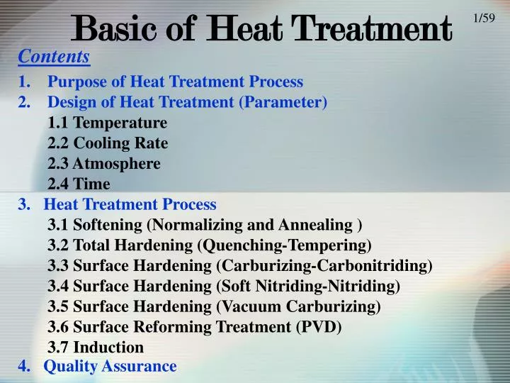
1/59. Contents. Purpose of Heat Treatment Process Design of Heat Treatment (Parameter) 1.1 Temperature 2.2 Cooling Rate 2.3 Atmosphere 2.4 Time 3. Heat Treatment Process 3.1 Softening (Normalizing and Annealing ) 3.2 Total Hardening (Quenching-Tempering)

E N D
1/59 Contents • Purpose of Heat Treatment Process • Design of Heat Treatment (Parameter) • 1.1 Temperature • 2.2 Cooling Rate • 2.3 Atmosphere • 2.4 Time • 3. Heat Treatment Process • 3.1 Softening (Normalizing and Annealing ) • 3.2 Total Hardening (Quenching-Tempering) • 3.3 Surface Hardening (Carburizing-Carbonitriding) • 3.4 Surface Hardening (Soft Nitriding-Nitriding) • 3.5 Surface Hardening (Vacuum Carburizing) • 3.6 Surface Reforming Treatment (PVD) • 3.7 Induction • 4. Quality Assurance Basic of Heat Treatment
Automotive Parts ชิ้นส่วนที่เกี่ยวกับระบบปรับอากาศ Car Cooler, Car heater, Car Air-conditioner, Compressor, Air-conditioner sensing system etc. ชิ้นส่วนที่เกี่ยวกับเครื่องยนต์ Engine Management System: EMS , Diesel System Electronic control, Starter, Alternator, Radiator etc. ชิ้นส่วนที่เกี่ยวกับการขับเคลื่อน ความปลอดภัย Antilock brake system (ABS), TractionControl System, Cruise Control System, Air bag sensing System, Vehicle Stability Control System (VSC) etc. 2/59 ชิ้นส่วนที่เกี่ยวกับตัวถัง Combined instrument , Wiper motor, Wireless Door Lock, Hone etc.
1. Purpose of Heat treatment process 3/59 ปริมาณที่สึก (Abrasion loss) ปรับปรุงความต้านทานในการกัดกร่อน (Improving wear resistance) Heat Treatment None HT HT Raw Material - Steel HT ปรับปรุงความแข็งแรงต่อความล้า (Improving fatigue strength) ความเครียด (Stress) None HT ปรับปรุงคุณสมบัติทางกล (Improving machinability property) Change Property จำนวนรอบ(Repeat cycle) ปรับปรุงคุณสมบัติในการขึ้นรูปเย็น (Improving cold press property) การปรับปรุงคุณสมบัติอื่นๆ (คุณสมบัติทางแม่เหล็ก เป็นต้น) Improving other property (Magnetic Property etc)
2. Design of Heat Treatment Process (Parameter) Temperature(C) Temp x Time Atmosphere Cooling Water Oil ・Carburizing, Decarburizing ・Deoxidation, oxidation In Furnace Air Normalizing Annealing Quenching Time 4/59 ► Customer Requirement/Specification (Hardness, Deformation, Appearance) ► Temperature: Fe-C Equilibrium phase diagram ► Cooling Rate: Continuous Cooling Transformation (CCT) ►Time : (Material Composition, Mass effect) ►Atmosphere : Depend on product requirements
2.2 Fe-C Equilibrium phase diagram 5/59 Use in Heat treatment process Fe-CEquilibrium diagram
2.2 TEMPERATURE γ (Acm Transformation) 910 (A3 Transformation) Temperature ( C ) γ+Fe3C γ+α 727℃(A1 Transformation) α α+Fe3C 0.8 % C (%) B A C 6/59 (A) Martensite (A) Matensite (Nitral 3% 15s) Material: C 0.88%, Si 0.28%, Mn 0.36%, P 0.020%, S 0.013% Condition: 850C x 30mins Quenching by water Tempering at 100 x 30mins (B) Martensite (Black)+ Ferrite (White) (B) Matensite + Ferrite (Nitral 3% 25s) Material: C 0.32%, Si 0.22%, Mn 0.70%, P 0.017%, S 0.021% Condition: 930C x 30mins Cooling by air and keep at 740 x 10 mins Quenching by water Tempering at 140 x 30mins (C) Matensite + Spheroidal cementite (Nitral 3% 14s) Material: C 1.16%, Si 0.24%, Mn 0.46%, P 0.013%, S 0.017% Condition: 800C x 30mins Quenching by water Tempering at 180 x 60mins (C) Martensite + Spheroidal cementite (White Spot)
2.3 Continuous Cooling Transformation (CCT) 7/59 (1) Martensite Continuous Cooling Transformation (CCT) Diagram (3) Maretnsite + Fine Pearrite (1) Matensite (Nitral 3% 15s) Material: C 0.88%, Si 0.28%, Mn 0.36%, P 0.020%, S 0.013% Condition: 850C x 30mins Quenching by water Tempering at 100 x 30mins (3) Matensite + Fine Pearrite (Nitral 3% 6s) Material: C 0.46%, Si 0.24%, Mn 0.69%, P 0.020%, S 0.022% Condition: 850C x 30mins Quenching by water (66-68C) (5) Pearrite (Nitral 3% 5s) Material: C 0.88%, Si 0.28%, Mn 0.36%, P 0.02%, S 0.013% Condition: 900C x 5Hrs Furnace Cooling (Full annealing) (5) Pearrite
9. ผลกระทบของความเร็วในการทำความเย็นที่ไม่เหมาะสม In Furnace Air ความยาวที่เปลี่ยนไป Oil Water อุณหภูมิ ( C ) ความสัมพันธ์ระหว่างขนาดของชิ้นงานกับ สิ่งที่ใช้ทำความเย็น 8/59 • ช้าเกินไป • ได้โครงสร้างที่ไม่ใช่แบบ MARTENSITE เช่น RETAINED AUSTENITE, FERRITE, PEARITE ทำให้ความแข็งลดลง • เร็วเกินไป • ทำให้ชิ้นงานบิดงอ หรือ แตกหักหลังการQUENCHING • ทำให้ขนาดของชิ้นงานเปลี่ยนไป อาจนำไปประกอบไม่ได้ • สิ่งที่ใช้ในการทำความเย็นในไทยโตเคนเทอร์โม • น้ำมันเย็น • น้ำมันร้อน • ก๊าซไนโตรเจน • อากาศ • เย็นในเตา 6. น้ำ
10. ผลของขนาด Core (OK) Surface (OK) 10/59 Core (NG) อุณหภูมิ สมการหาค่าคงตัว (K) K = 1000 x C% + 500 x Mn% + 1000 x Ni% + 400 x Cr% Surface (OK) เวลา วัสดุ ความแข็งหลังการ QUENCHING ขนาดสูงสุด S15C 40 - 45 Ø 5.0 mm S35C 52 - 56 Ø 10.0 mm SCM415 40 - 45 Ø 40.0 mm SCM435 52 - 56 Ø 50.0 mm Ramark : Hardness = 60√C + HRC20
3 Heat Treatment Process 11/59 Heat treatment process Quenching Tempering Precipitation Hardening Total Hardening Improving Mechanical property Carburizing (Carbonitriding)Quenching Soft Nitriding Nitriding Sulfurizing (Nitriding) Local hardening [Induction・Laser・Electron beam] Carbide Film coating,diffusion treatment Wear Resistance Fatigue Resistance Strength Surface Hardening Heat Treatment Deposition (PVD,CVD) ion implantation etc Surface Reforming Treatment Improving workability and other property Full anneal Spheroidizing annealing Stress relief annealing Grain refinement annealing Magnetic annealing Normalizing Machinability Forgeability Stress relief Magnetic properties Microstructure realignment
Annealing and Normalizing Annealing The purpose of annealing is to refine the grain, induce softness, remove residual stresses due to heavy machining, improve the machinability. Normalizing Batch Type The basic purpose of normalizing is to produce a harder and stronger steel than full annealing, to refine the grain, homogenize the structure and improve machinability. Company’s Equipment - Batch Type Furnace: 5 Sets - Continuous Type Furnace: 2 Sets Continuous Type 12/59
13. Normalizing อุณหภูมิที่เหมาะสม (เหนือเส้น A3) A เวลาในการอบชุบ ที่เหมาะสม (ขนาดของงาน) B 13/59 วัตถุประสงค์ เนื่องจากชิ้นงานที่ผ่านการขึ้นรูปร้อน เช่น การรีด (Hot rolling) การตีขึ้นรูป (Hot Forging) เหล็กจะถูกเผาในอุณหภูมิที่ค่อนข้างสูง ทำให้โครงสร้างมี Grain ใหญ่ ไม่สวย และมีขนาดไม่เท่ากัน จุดประสงค์ของขบวนการนี้ คือ จะเพิ่มความร้อนในชิ้นงานอีกครั้ง เพื่อทำโครงสร้างให้มีขนาดมาตรฐานที่เท่าๆกัน ทำให้ขึ้นรูปได้ง่าย วิธีการ ขบวนการ Normalizing คือการเพิ่มความร้อนโดยใช้อุณหภูมิที่เหนือกว่าเส้น A3โดยมีวัตถุประสงค์ที่จะปรับปรุงโครงสร้าง(Normalizing =ทำให้กลับสู่สภาพปกติทำให้เป็นมาตรฐาน) แล้วทำการปล่อยทิ้งไว้ให้เย็นในอากาศ เย็นตัวในอากาศ อนึ่งจะใช้ขบวนการ Normalizing กับเหล็กที่มีธาตุคาร์บอนต่ำ
14. Annealing 14/59 การAnnealingมี3วิธีด้วยกัน คือ 1. การอบอ่อนอย่างสมบูรณ์ (Full Annealing) 2. การอบอ่อนเพื่อความอ่อนตัวสูง (Spheroidizing) 3. การอบอ่อนเพื่อขจัดความเครียดเหลือค้าง (Stress relief)
Full Annealing อุณหภูมิที่เหมาะสม (เหนือเส้น A3) A เวลาในการอบชุบ ที่เหมาะสม (ขนาดของงาน) B 15/59 วัตถุประสงค์ การอบอ่อนอย่างสมบูรณ์ (Full Annealing) เป็นขบวนการที่ทำเพื่อเปลี่ยนคุณสมบัติของเหล็กคาร์บอนปานกลางให้มีความอ่อนตัวสูง เพื่อช่วยให้กลึงหรือไสได้ง่ายขึ้น วิธีการ ขบวนการนี้ทำได้โดยการเพิ่มความร้อนให้กับชิ้นงาน(สูงกว่าเส้นA3)จนเปลี่ยนโครงสร้างเป็นโครงสร้างแบบ Austenite หลังจากนั้นปล่อยให้ชิ้นงานเย็นตัวลงอย่างช้าๆโครงสร้างหลังการอบชุบจะเป็นโครงสร้างแบบ FERRITE+PEARLITE เย็นตัวในช้าๆ FERRITE+PEARLITE
Stress Relief อุณหภูมิที่เหมาะสม (ต่ำกว่าเส้นA1) A เวลาในการอบชุบ ที่เหมาะสม (ขนาดของงาน) B 16/59 วัตถุประสงค์ การอบอ่อนเพื่อขจัดความเครียดเหลือค้าง (Stress relief)ขบวนการนี้ทำเพื่อขจัดความเครียด(Stress)ภายในชิ้นงาน ในกรณีของชิ้นงานขึ้นรูปเย็น(ดัดให้โค้งงอ,กด เป็นต้น)บริเวณที่ดัดหรือกดดังกล่าวจะเกิดความแข็งและความเครียดสูงกว่าบริเวณอื่นๆในกรณีที่ไม่ทำการคลายเครียดให้กับชิ้นงานอาจเกิดการงอหรือแตกร้าวในบริเวณดังกล่าวได้เพื่อป้องกันเหตุการณ์เหล่านี้จึงต้องทำการ Stress relief วิธีการ เย็นตัวช้าๆ *การอบชุบด้วยขบวนการนี้ไม่เกิดการเปลี่ยนแปลงโครงสร้าง เนื่องจากการเพิ่มอุณหภูมิความร้อนที่ต่ำกว่าเส้นA1
Spheroidizing 17/59 วัตถุประสงค์ การอบอ่อนเพื่อความอ่อนตัวสูง (Spheroidizing) จะเปลี่ยนคุณสมบัติของเหล็กคาร์บอนสูงให้มีความแข็งตัวลดน้อยลงการอบชุบด้วยกระบวนการนี้จะทำให้ธาตุคาร์บอนเปลี่ยนเป็นทรงกลมซึ่งจะเรียกการเปลี่ยนแปลงนี้ว่า Spheroidizingวัตถุประสงค์ของกระบวนการนี้ก็เพื่อแปรรูปเหล็กที่มีธาตุคาร์บอนสูงให้มีสภาพที่อ่อนตัวลงและเป็นการป้องกันการเปลี่ยนรูปในขณะทำการQuenching and Tampering (QT),การแตกหักหลังจากทำการQT,และ ขบวนการSpheroidizing เป็นขบวนการที่สามารถปรับเปลี่ยนความแข็งของชิ้นงานให้ได้ต่ำที่สุด เป็นการเพิ่มประสิทธิภาพในการผลิตของชิ้นงานขึ้นรูปเย็น(ขึ้นเกลียวน็อต,การขึ้นรูปแบบงอ) นอกจากนั้นขบวนการนี้ยังถูกนำไปใช้กับเหล็กคาร์บอนปานกลางอีกด้วย วิธีการ การนำเหล็กไปเผาที่อุณหภูมิประมาณเส้น A1และรักษา อุณหภูมินั้นไว้สักระยะหลังจากนั้นปล่อยให้เย็นตัวลงอย่างช้าๆ อุณหภูมิที่เหมาะสม (ที่เส้นA1) A A1 เวลาในการอบชุบ ที่เหมาะสม (ขนาดของงาน) B เย็นตัวช้าๆ SPHEROIDIZING
Temperature (Annealing and Normalizing) γ (Acm Transformation) Normalizing 910 (A3 Transformation) Temperature ( C ) Full Annealing γ+α α 727℃(A1 Transformation) Spheriodizing α+Fe3C Stress Relief 0.8 % C (%) 18/59
Normalizing and Annealing Process 19/59 Purpose: Improving machining ability Process Purpose Material Cooling Media Microstructure Normalizing Softening, Microstructure realignment Low Carbon Air Pearrite+Ferrite Full Annealing Softening Middle Carbon In Furnace Pearrite+Ferrite Spheroidizing Softening High Carbon In furnace Air Spheroiding Stress Relief Stress Relief All Air Pearrite+Ferrite, Spheroiding
3. วิธีการทำให้เกิดความแข็ง Fe Fe Fe Fe Fe Fe Fe Fe Mo C Cr 20/59 (1) Phase Transformation by Quenching (2) Solution Hardening Quenching Martensite (3) Diffusion Bonding (4) Work Hardening Compound Layer (Fe3N) Bend ----> Broke
Hardening and Tempering HARDENING The basic purpose of hardening is to produce a fully martensitic structure by controlling cooling rate, how fast a steel must be cooled in order to form only martensite. TemperING Batch Type The purpose of tempering is to relieve residual stresses and to improve the ductility and toughness of the steel. Company’s Equipment - Batch Type Quenching Furnace: 20 Sets - Continuous Type Quenching Tempering Furnace: 7 Sets Continuous Type 21/59
Total Hardening (Quenching-Tempering) Hardness (HRC) No Temper Tempering Temperature (C x 1 hr) SK5, SKS43, SKS44’s Tempering Hardness (Water Cooling Keep 20 Mins) 22/59 ►Quenching Temperature (Material) A Time (Size) C Cooling rate (Deformation-Hardness) B Quenching Martensite ►Tempering
Tempering Hardness (HRC) No Temper Tempering Temperature (C x 1 hr) SK5, SKS43, SKS44’s Tempering Hardness (Water Cooling Keep 20 Mins) 23/59 ข้อควรระวังมีช่วงอุณหภูมิที่ทำการอบคืนที่ทำให้ค่าความทนทานในการกระแทกลดลงคือ 250 – 400ċ (Low-temperature Temper Brittleness), 500 – 600ċ (High-temperature Temper Brittleness) Low-temperature Temper Brittleness High-temperature Temper Brittleness
Tempering 24/59 Martensite Troostite Sorbite
Carburizing – Carbonitriding - Soft Nitriding This kind of heat treatment change the chemical composition by the addition of carbon, nitriding by the addition of nitrogen and cyaniding by the addition of both carbon and nitrogen. The purpose of this process is to produce a hard layer on the surface (a hard wear-resistant surface) and relative soft, though inside. Batch Type Sub-zero Continuous Type 25/59 Company’s Equipment - Batch Type Quenching Furnace: 20 Sets - Continuous Type Quenching Tempering Furnace: 1 Sets
Surface Hardening (Carburizing-Carbonitriding) 26/59 ( Carbon % and Hardness from Surface ) Gas Carburizing Furnace Converted gas (Mixed gas: CO,H2,N2) 0.8 Carbon at surface is high Carbon(%) 0.6 Carburizing Gas Control atmosphere by C3H8 and Air 0.4 Carbon at core is low (Material’s carbon compound) 0.2 0 Surface is hard Carburizing Room 800 Hardness(H v) 600 Core is soft 400 Control CP at Eutectoid Point (0.8%) 200 Oil Tank 0 0.5 1.0 0 Depth from surface (mm.) Carburizing (Material SCM415,SCM420,SCr415,SCr420) Carbonitriding (Material SPCC, S10C, S15C, S20C)
Carburizing Temperature, Time and case-depth 27/59 Case-depth (mm.) D = K√T D : Case-depth K : Temperature dependent constant value T : Time Carburizing Time (Hrs.) Remark : F.E.Harris Formula Relationship between Case-depth and Time
Carburizing (Carbonitriding) Quenching-Tempering 28/59 Characteristic ①เป็นวิธีการอบชุบโดยเพิ่มปริมาณคาร์บอนที่ผิว (0.8%)เพื่อเพิ่มความแข็งผิวของเหล็กคาร์บอนต่ำ และ เหล็กผสมคาร์บอนต่ำ ②ในกรณีของขบวนการก๊าซคาร์โบไนไทรดิงค์ การซึมของไนโตรเจน ก็จะเป็นลักษณะเดียวกันกับคาร์บอน ③เพิ่มความแข็ง เพิ่มคุณสมบัติในการต้านทานการสึกกร่อน เพิ่มความแข็งแรงต่อการล้า 910 C Condition Temperature ( C ) C D 850 C P Quenching Tempering 200 C (CP1.1%) (CP0.8%) Time (Hrs.) Gas carburizing … Low Carbon Alloy-steel (SCr415、SCr420、SCM415、SCM420) Gas carbonitring …Low Carbon C-steel (SPCC, S10C, S15C, S20C ) Material
Point of Carburizing-Quenching 29/59 1. เซ็ทค่าความหนาแน่นของคาร์บอนที่ 0.70 – 0.85 % 2. ความหนาของชั้นความแข็งที่ต้องต่ำกว่า 30%ของขนาดชิ้นงาน 3. ความแข็งของส่วนที่เป็นเกลียวโดยทั่วไปจะไม่ให้แข็งเกิน HRC35 (ทำการป้องกันการเกิดCarburizing ที่ส่วนเกลียว) 4. วัสดุที่มีปริมาณคาร์บอนเกิน 0.23%ไม่สามารถที่จะเข้ากระบวนการนี้ได้ 5. เหล็กผสมไม่สามารถเข้ากระบวนการ GNC ได้ SPCC, S10C, S15C, S20C … GNC SCr415, 420, SCM415, 420 … GC 6. ควรระวังการเกิด การแตกร้าว การลดลงของความแข็ง การเกิดการชุบแข็งอีกครั้ง จากเงื่อนไขในการขัด 7. ถ้าขัดมากเกินกว่าปริมาณที่กำหนดไว้อาจทำให้ค่าความแข็งต่ำลง 8. ข้อกำหนดของชิ้นงานด้านขนาดที่มีความละเอียดระดับ mm ต้องทำการ Sub-zero หลังการ Quenching
Surface Hardening ( Soft Nitriding – Nitriding) 30/59 Characteristic 1. Make Hard compound layer at surface by change material composition (Put N and/or C) 2. Improving wear resistance 3. Use low temperature (Decrease deformation) Condition Soft nitriding 570 C Temperature ( C ) Converted gas (Mixed gas: CO,H2,N2) + NH3 Oil Cooling Material * Soft Nitriding (Material: All) * Nitriding (Material: High Al, Cr, Ti for example SCM, SACM)
Combination between Heat treatment Process and material 31/59 Process Atmosphere control Hardness (Hv) Mateiral Gas carburizing Rx 100% NH3 0% HRC 57 – 65 SCr415,420 SCM415,420 etc Gas Carbonitriding-QT Rx 95% NH3 5% HRC 57 – 65 SPCC, S10C, S15C, S20C etc Soft Nitriding Rx 50% NH3 50% 4 – 20 mm All - Steel Nitriding Rx 0% NH3 100% Up to time 0.2-0.3 mm (50-100Hrs) High Al, Cr, Ti for example SCM, SACM etc
32/59 EVC21Vacuum Carburizing furnace
What is the Vacuum Carburizing hardening? 33/59 The Vacuum Carburizing hardening is that : Method of Carburizing hardening which executes under decompression condition by the gas of hydrocarbon system. And, compared with the past "Gas carburizing hardening" ・Improvement of productivity and energy saving ⇒ decrease of cost ・Decrease of surface abnormal layer ⇒ High strength Gas carburizing Vacuum carburizing Rxgas+enriching gas Hydrocarbon system gas(C3H8,C4H10,C2H4,C2H2) Always(about15Nm3/h) Total 60Nm3 Only about 30 minute/ch at carburizing (~about5Nm3/h) Total2Nm3 Pressure:101kPa(Atmospheric pressure) Composition:CO+CO2+N2+H2+H2O Pressure :1~10kPa(Decompression) Composition:C2H2+C2H4+CH4+H2 others Vacuum pump <carburizing mechanism>(equilibrium carburizing ) < carburizing mechanism (example)> (supersaturation carburizing ) C2H2 1/2C2H4 H2 CO CO CO2 Fe3C Fe3C C work work C C C
Experiment result 34/59 930℃Gas carburizing K value of depth of effective hardening layermm carburizing time h 930℃Vacuum carburizing 1040℃ Vacuum carburizing Temperature ℃ 930℃ Depth of effective effect layermm Density of surface carbon % 1040℃ Depth of effective hardening layer mm Explanation Coefficient of carburizing mm (Diffusion) /(carburizing) time ratio Carburizing time h
Minute hole nozzle 35/59 Diesel engine Fuel injection nozzle SCM415 Hole diameter6mm Nozzle diameter0.2mm Vacuum carburizing has been delivered. Section hardness distribution curve Outer part Inner part Seat Minute hole carburizing is excellent.
Induction Induction Induction hardening is shallow-hardening methods and do not change the composition of the steel but hardening the surface. Induction hardening is applied mainly to medium-carbon steels. The part to be induction-hardened is be made the secondary of high-frequency induction apparatus. Progressive surface hardening by the induction heating may be applied successfully to relatively long pieces of uniform cross section such as chain-saw blades and long lead screws. Company’s Equipment - Induction: 4 Sets 36/59
Induction Induction Induction hardening is shallow-hardening methods and do not change the composition of the steel but hardening the surface. Induction hardening is applied mainly to medium-carbon steels. The part to be induction-hardened is be made the secondary of high-frequency induction apparatus. Progressive surface hardening by the induction heating may be applied successfully to relatively long pieces of uniform cross section such as chain-saw blades and long lead screws. Company’s Equipment - Induction: 4 Sets 37/59
Quenching-Tempering by Induction 38/59 Characteristic • Process Time is short (Protecting Decarburize and Carburizing) • Quenching/tempering some area (Local Hardening) and easy to install in production-line • Surface is hard / Core is softor otherwise - Induction hardening is applied mainly to medium-carbon steels. - The part to be induction-hardened is be made the secondary of high-frequency induction apparatus and quenching quickly by water. Method Microstructure at core (Did not quenching) Microstructure after Quenching
Physical Vapor Deposition (PVD) 39/59 Arc Power Supply + - Target Cathode Pumping Anode ทำให้เป็นสูญญากาศ + Heater Arc Power Supply - Rotation Table Process Gas ใช้ N2เป็นก๊าซบรรยากาศ - Bias Electrode Remark : PVD by ARC method +
PVD 40/59 ชนิด ความแข็ง (Hv) อุณหภูมิอบชุบ คุณลักษณะ สี TiN 2000 500C ทนทานต่อแรงเสียดสี สวยงาม ทอง TiCN 2500 500C ทนทานต่อแรงเสียดสี เทาเงิน CrN 1600 350C ลื่น(ลดการเสียดสี) ทนทานต่อการกัดกร่อน เงิน TiAlN 3000 500C ทนทานต่อความร้อน ม่วง
การวัดคุณภาพ 41/59 OK NG รอยกดด้วยRockwel การวัดความหนาของชั้น COATING Sketch Test การวัดการเกาะยึดของชั้นที่ทำการCOATING
4. How to assure quality 42/59 การตรวจสอบความแข็ง 1. Brinell Hardness Tester (HB) 2. Rockwell Hardness Tester (HRA,HRB,HRC) 3. Vickers Hardness Tester (Hv) 4. Knoop Hardness Tester (HK) การตรวจสอบ แบบทำลาย 5. Shore Hardness Tester (HS) การตรวจสอบโครงสร้าง 1. Microscope 2. Scanning Electron Microscope: SEM การตรวจสอบคุณสมบัติ ทางกลของวัสดุ 1. Tensile test 2. Bending Test 3. Torsion Test 4. Impact Test 5. Fatigue Test 1. Liquid Penetrant Test การตรวจสอบ แบบไม่ทำลาย 2. Magnetic Test 3. Ultrasonic Test
Hardness Tester คืออะไร ? 43/59 Hardness หรือ ความแข็ง เป็นปริมาณทางฟิสิกส์ที่แสดงถึงความสามารถในการคงรูปของวัสดุต่างๆ เมื่อมีแรงภายนอกหรือโหลดมากระทำกับวัตถุนั้นๆ ความแข็งเป็นปริมาณสัมพัทธ์ที่มีความแตกต่างจากปริมาณทางฟิสิกส์อื่นๆ เช่น ระยะทาง เวลา ปริมาตร หรือกระแสไฟฟ้า ตรงที่ไม่มีจำนวนหรือมาตรฐานที่แน่นอน แต่จะขึ้นอยู่กับลักษณะเฉพาะทางกายภาพอย่างอื่น เช่น tensile strength, yield strength, ขีดจำกัดความยืดหยุ่น ความต้านทานการเกิดรอย เป็นต้น ความแข็งของวัสดุจึงกลายเป็นปัจจัยสำคัญในการควบคุมคุณภาพของผลิตภัณฑ์ การคำนวณน้ำหนัก ความดัน หรืออุณหภูมิ เพื่อที่จะดูว่าวัสดุนั้นมีความสามารถในการยืดหยุ่นได้หรือไม่เป็นสิ่งที่ยุ่งยาก การวัดค่าความแข็งเป็นหนึ่งในวิธีการดังกล่าวที่ดูเหมือนจะเป็นวิธีที่ง่ายและดีที่สุดHardness Tester จึงเป็นเครื่องมือที่ใช้ในการวัดและทดสอบค่าความแข็งนั่นเอง
เราใช้เครื่องมือในการวัดความแข็งวัดอะไรได้บ้างเราใช้เครื่องมือในการวัดความแข็งวัดอะไรได้บ้าง 44/59 1. ความแข็งผิว (SURFACE HARDNESS) 2. ความแข็งภายใน (CORE HARDNESS) 3. ความลึกผิวแข็ง (CASE-DEPTH) 3.1 EFFECTIVE CASE-DEPTH (513, 550) 3.2 TOTAL CASE-DEPTH
เทคนิคการทดสอบความแข็งเทคนิคการทดสอบความแข็ง 45/59 เดิมเทคนิคในการทดสอบความแข็งมีด้วยกัน 3 วิธี คือ Brinell Hardness, Rockwell Hardness และ Vickers Hardness ซึ่งการทดสอบจะวัดความลึกของหัวกดที่จมลงไปในเนื้อวัสดุ ภายใต้แรงกดและระยะเวลาที่กำหนด ในปัจจุบันวิธีการวัดความแข็ง ได้แก่ Rockwell Hardness, Brinell Hardneess, Vickers Hardness, Knoop Hardness และ Shore Rockwell Hardness Tester เป็นวิธีการวัดความแข็งโดยการวัดและเปรียบเทียบความลึกของรอยกดบนพื้นผิววัสดุเมื่อมีแรงกดขนาดต่างๆ มากระทำ ซึ่งจะแบ่งออกเป็น 2 ช่วง คือ แรงกดนำ (preload) ขนาด 10 กิโลกรัม สำหรับการทดสอบแบบปกติ และขนาด 3 กิโลกรัม เพื่อทำการทดสอบพื้นผิว และใส่เพิ่มเข้าไปให้ได้ แรงกดเต็ม (full load) เป็น 60, 100 หรือ 150 สำหรับการทดสอบแบบปกติ และ 15, 30 หรือ 45 เพื่อการทดสอบพื้นผิว แล้วทำการคำนวณค่าความแข็ง Rockwell หัวกดที่ใช้อาจเป็นลูกเหล็กกลมที่มีเส้นผ่านศูนย์กลางขนาดต่างๆ หรือรูปกรวยที่มีมุม 120 องศา และมีเพชรทรงกลมขนาดรัศมี 0.2 มิลลิเมตรอยู่ที่ปลาย การทดสอบแบบนี้เป็นการทดสอบที่ง่าย รวดเร็ว เหมาะสำหรับชิ้นงานที่มีความแข็งสม่ำเสมอตลอดชิ้นงาน
Hardness Tester 46/59 BrinellHardness Tester ใช้ลูกเหล็กทรงกลมกดลงไปในชิ้นงานโดยใช้แรง 3000 Kg.f แล้ววัดขนาดของรอยกด นำค่าที่ได้นั้นไปแปลงเป็นค่าความแข็ง เหมาะสำหรับชิ้นงานที่มีความแข็งสม่ำเสมอตลอดชิ้นงาน
Hardness Tester 47/59 Vickers Hardness Tester เทคนิคนี้เป็นการพัฒนามาจากการทดสอบแบบ Brinell เพื่อลดปัญหาของความถูกต้องในการวัด หัวกดที่ใช้ในวิธีการนี้ คือ เพชร ซึ่งมีรูปร่างเป็นปิระมิดฐานสี่เหลี่ยมจัตุรัส และมีมุมระหว่างผิวหน้าด้านตรงข้ามกันเท่ากับ 136 องศา แรงกดที่ใช้อยู่ระหว่าง 1 กรัม - 100 กิโลกรัม ใช้ระยะเวลากดประมาณ 10-15 วินาที รอยที่เกิดขึ้นมีขนาดเล็กในระดับไมครอนจึงต้องอาศัยกล้องจุลทรรศน์ในการช่วยคำนวณความแข็งค่าความแข็งที่ได้จะแสดงออกมาดังเช่น 800 HV/10 ซึ่งหมายถึง มีค่าความแข็ง Vickers 800 และใช้แรงกด 10 กิโลกรัม ค่าความแข็งที่ได้จากวิธีการนี้จะให้ผลที่ชัดเจนและเป็นรูปแบบมากกว่าวิธีการอื่นๆ และสามารถใช้ทดสอบวัสดุได้อย่างหลากหลายทั้งที่มีองค์ประกอบสม่ำเสมอและไม่สม่ำเสมอ
Hardness Tester 48/59 Knoop Hardness Tester วิธีการนี้จะคล้ายคลึงกับวิธี Vickers แต่หัวกดที่ใช้เป็นเพชรรูปร่างปิระมิดที่มีมุมเป็น 130 องศา และ 172 องศา 30 ลิปดา เนื่องจากหัวกดมีลักษณะเรียวยาวจึงสร้างรอยกดที่มีความยาวของเส้นทแยงมุมมากกว่าวิธีการอื่นๆ ถึง 7 เท่า ทำให้สามารถเห็นภาพรอยกดได้อย่างชัดเจนแม้ใช้แรงกดต่ำ เทคนิคนี้จึงเหมาะสำหรับการทดสอบฟิล์มบาง หรือวัสดุที่เปราะแตกง่าย รวมถึงการทดสอบสมบัติที่ขึ้นอยู่กับทิศทาง (anisotropy) ได้ Shore Hardness Tester เป็นอุปกรณ์ที่ใช้ในการคำนวณความแข็งของวัสดุในเทอมของความยืดหยุ่น โดยหัวกดที่มีปลายเป็นเพชรจะถูกปล่อยออกจากตำแหน่งความสูงที่กำหนดลงบนส่วนที่ต้องการทดสอบ ค่าความแข็งจะขึ้นอยู่กับความสูงของหัวกดที่กระดอนกลับ วัสดุที่มีความแข็งมาก หัวกดก็จะกระดอนสูง
อ้างอิงเกี่ยวกับเครื่องมือวัดความแข็งอ้างอิงเกี่ยวกับเครื่องมือวัดความแข็ง 49/59
อ้างอิงเกี่ยวกับเครื่องมือวัดความแข็งอ้างอิงเกี่ยวกับเครื่องมือวัดความแข็ง 50/59