Download
1 / 13
220 likes | 1.23k Views
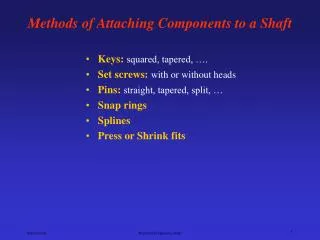
Methods of Attaching Components to a Shaft. Keys: squared, tapered, …. Set screws: with or without heads Pins: straight, tapered, split, … Snap rings Splines Press or Shrink fits. Keys. Hub. Shaft. ANSI standard. w. L. w = d /2, L = 2 d. Keys. ANSI standard. d = D / 10.

E N D
Methods of Attaching Components to a Shaft • Keys:squared, tapered, …. • Set screws:with or without heads • Pins:straight, tapered, split, … • Snap rings • Splines • Press or Shrink fits Mechanical Engineering Dept.
Keys Hub Shaft Mechanical Engineering Dept.
ANSI standard w L w = d/2, L = 2d Keys Mechanical Engineering Dept.
ANSI standard d = D / 10 Pins and Keys could be used as a mechanical fuse, they shear off to protect the drive train. Pins and keys weaken the shaft and create stress concentration. T = πd 2 D Ssy / 4 Pins Torque capacity τxy = Force / shear area = (Torque)(radius) / 2(πd 2/4) = Ssy (shear strength) Mechanical Engineering Dept.
ANSI standard Maximum safe holding force d = D/8 + 5/16 F = 2500 ( d ) 2.31 D = shaft diameter d = set screw diameter Use safety factor of 2.5 Set Screws Mechanical Engineering Dept.
Retaining (Snap) Rings Snap rings are used to prevent the axial motion of mating concentric components such as gear hubs and shafts. Material; SAE 1060-1090 spring steel, beryllium copper alloy 25, stainless steel, or aluminum. Refer to catalog for size and groove dimensions. Mechanical Engineering Dept.
l = spline length T = Ssy(πdp2 l) / 16 rp = pitch radius , Ssy = yield strength in shear Splines Splines may be considered as using multiple keys, integral with the shaft. Best way to transmit large torque. See ANSI or SAE standards for dimensions τxy = Force / (shear area /4), SAE assumption that only 25% of teeth are actually sharing the load at any one time. τxy = 4F / A = (4T) / (rpA) = (8T) / (dpA) = (16T ) / (πdp2 l) = Ssy Mechanical Engineering Dept.
Press or Shrink Fits Interference Fit– shaft diameter is slightly larger than hub diameter. Inexpensive and semi-permanent connection. Allowance always equals smallest hole minus largest shaft. Mechanical Engineering Dept.
Press or Shrink Fits Mechanical Engineering Dept.
Press or Shrink Fits When two cylindrical parts are assembled by shrinking or press-fitting one part on another, contact pressure is created between the two parts. Thick-walled cylindrical pressure vessel equations are used to derive the equation relating the contact pressure to the interference. δ = pR / E [(2R2 (ro2 – ri2) / (ro2 – R2)(R2 –ri2)] δ= radial interference , p = contact pressure Mechanical Engineering Dept.
FN3 fit δmax = radial interference = .0032/2 = .0016, tightest fit + .0012 Hole = 2.0000 δmin = radial interference = .0013/2 = .00065, loosest fit + .0000 + .0032 Shaft = 2.0000 + .0025 Max diametral interference = .0032 - .0000 = .0032 Min diametral interference = .0025 - .0012 =.0013 Example Press or Shrink Fits Class FN3 is used to press fit a hub onto a shaft. Determine the torque that can be transmitted. The shaft diameter is 2.0 in. and hub diameter is 3.0 in. and has a length l = 2 in. 2.0 R 3.0 2.0 ro shaft hub p = contact pressure, R = contact radius = 1.0 in., ro = hub radius = 1.5, ri = shaft inside radius = 0, and δ = radial interference Mechanical Engineering Dept.
Press or Shrink Fits δ = pR / E [(2R2 (ro2 – ri2) / (ro2 – R2)(R2 –ri2)] pmax = 13,333 psi and pmin = 5417 psi Torque capacity μ = coefficient of friction, steel on steel (dry) .15 μF = friction force between the outside surface of the shaft and the inside surface of the hub F = (contact pressure)(contact area) Torque = (μF) R, F = p (2πRl) Torque = (μp 2πRl) R = (.15)(5417)(2π)(1)(2)(1) = 10,210 lb-in hp = Tω / 63000 = (10210)(1800)/63000 = 290 Mechanical Engineering Dept.
Various Methods of Attaching Components to a Shaft Mechanical Engineering Dept.