Download
1 / 76
810 likes | 1.65k Views
Examining the ATM Requirements Document. A requirements document specifies the overall purpose of a system and what it must do. A small local bank intends to install a new ATM. Automated teller machine user interface. . Cash Dispenser. Deposit Slot.

E N D
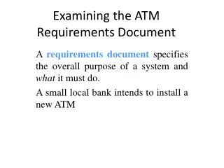
Examining the ATM Requirements Document A requirements document specifies the overall purpose of a system and what it must do. A small local bank intends to install a new ATM
Automated teller machine user interface. Cash Dispenser Deposit Slot
Examining the ATM Requirements Document (Cont.) • The ATM should have the following functionality. • Stories Cards • The screen prompts the user to enter an account number. • The user enters a five-digit account number, using the keypad. • For authentication purposes, the screen prompts the user to enter the PIN. • The user enters a five-digit PIN, using the keypad. • If the user enters a valid account number and the correct PIN for that account, the screen displays the main menu.
Examining the ATM Requirements Document (Cont.) • The main menu (see Figure) displays a numbered option for each of the three types of transactions, and the option to exit the system.
Examining the ATM Requirements Document (Cont.) • The user enters 2 to make a withdrawal (see Figure). • If the user enters 1, the screen displays the user’s account balance from the bank’s database.
Examining the ATM Requirements Document (Cont.) • The user enters 3 to make a deposit: • The screen prompts the user to enter a deposit amount. • The screen displays a message telling the user to insert a deposit envelope into the deposit slot. • If the deposit slot receives a deposit envelope, the ATM credits the deposit amount to the user’s account balance in the bank’s database.
Examining the ATM Requirements Document (Cont.) • Requirements gathering might include interviews with potential users of the system and specialists in fields related to the system. • The software life cycle specifies the stages through which software evolves from the time it is conceived to the time it is retired from use. • Waterfall models perform each stage once in succession. • Iterative models may repeat one or more Releases several times throughout a product’s life cycle.
Examining the ATM Requirements Document (Cont.) • To capture what a proposed system should do, developers often employ a technique known as use case modeling. • Use cases represent different capabilities that the system provides to its clients. • The simplified ATM system we build in this case study requires only the first three use cases (see Figure).
Examining the ATM Requirements Document (Cont.) Use Case Diagrams • A use case diagram models the interactions between a system’s clients and the system. • Figure shows the use case diagram for our ATM system.
FigureUse case diagram for the ATM system from the user’s perspective.
Examining the ATM Requirements Document (Cont.) • The stick figure represents an actor, which defines the roles that an external entity—such as a person or another system—plays when interacting with the system.
Examining the ATM Requirements Document (Cont.) • A design specificationshould specify how the system should be constructed to satisfy the system requirements. • Asystemis a set of components that interact to solve a problem. • For example, to perform the ATM system’s designated tasks, our ATM system has a user interface, contains software that executes financial transactions and interacts with a database of bank-account information. • Systemstructuredescribes the system’s objects and their interrelationships. • Systembehaviordescribes how the system changes as its objects interact with one another.
Identifying the Classes in the ATM Requirements Document • We create classes only for the nouns and noun phrases in the ATM system (see Figure). • We do not need to model some nouns such as “bank” which are not part of the ATM operations.
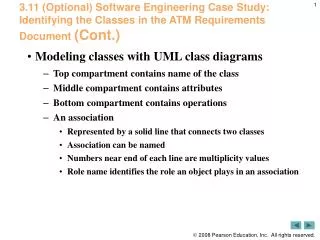
Identifying the Classes in the ATM Requirements Document (Cont.) • UML class diagrams model the classes in the ATM system and their interrelationships (see Figure). • The top compartment contains the name of the class. • The middle compartment contains the class’s attributes. • The bottom compartment contains the class’s operations.
Identifying the Classes in the ATM Requirements Document (Cont.) • Figure shows how our classes ATM and Withdrawal relate to one another. • The line that connects the two classes represents an association. • Multiplicity values indicate how many objects of each class participate in the association. • One ATM object participates in an association with either zero or one Withdrawal objects. • currentTransaction is a role name, which identifies the role the Withdrawal object plays.
Identifying the Classes in the ATM Requirements Document (Cont.) Figure Multiplicity Types
Identifying the Classes in the ATM Requirements Document (Cont.) • In Figure, the solid diamonds indicate that class ATMhas a composition relationship with classes Screen, Keypad, CashDispenser andDepositSlot. • Composition implies a whole/part relationship—the ATM “has a” screen, a keypad, a cash dispenser and a deposit slot. • The has-a relationship defines composition.
Identifying the Classes in the ATM Requirements Document (Cont.) • Composition relationships have the following properties: • Only one class in the relationship can represent the whole. • The parts in the composition relationship exist only as long as the whole. • A part may belong to only one whole at a time. • If a “has-a” relationship does not satisfy one or more of these criteria, hollow diamonds are used to indicate aggregation.
Identifying the Classes in the ATM Requirements Document (Cont.) • Figure shows a class diagram for the ATM system. • The class diagram shows that class ATM has a one-to-one relationship with class BankDatabase. • We also model that one object of class BankDatabase participates in a composition relationship with zero or more objects of class Account.
Identifying Class Attributes in the ATM System • A person’s attributes include height, weight and whether the person is left-handed, right-handed or ambidextrous. • We can identify attributes of the classes in our system by looking for descriptive words and phrases in the requirements document.
Figure Descriptive words and phrases from the ATM requirements document
Identifying Class Attributes in the ATM System (Cont.) • The class diagram in Figure lists some of the attributes for the classes in our system. • We list each attribute’s name and type, followed in some cases by an initial value. Figure Classes with attributes.
Identifying Class Attributes in the ATM System (Cont.) • Consider the userAuthenticated attribute of class ATM: userAuthenticated : bool = false • This attribute declaration contains: • the attribute name, userAuthenticated. • the attribute type, bool. • an initial value for an attribute,false. Software Engineering (Agile Approach) Early in the design process, classes often lack attributes(and operations). Such classes should not be eliminated, however, because attributes (and operations) may become evident in the later phases of design and implementation.
Identifying Objects’ States and Activities in the ATM System • Each object in a system goes through a series of discrete states. • An object’s state is indicated by the values of its attributes at that time. • State machine diagrams model key states of an object and show under what circumstances the object changes state.
Identifying Objects’ States and Activities in the ATM System (Cont.) • Figure is a simple state machine diagram that models two of the states of an object of class ATM. FigureState machine diagram for some of the states of the ATM object.
Software Engineering Observation(Agile Approach) • Software designers do not generally create state machine diagramsshowing every possible state and state transition for all attributes—thereare simply too many of them. State machine diagrams typically show onlythe most important or complex states and state transitions.
Identifying Objects’ States and Activities in the ATM System (Cont.) • An activity diagram models an object’s workflow during application execution. • The activity diagram in Figure models the actions involved in executing a BalanceInquiry transaction.
Identifying Objects’ States and Activities in the ATM System (Cont.) FigureActivity diagram for a BalanceInquiry transaction
Identifying Objects’ States and Activities in the ATM System (Cont.) • Figure shows an activity diagram for a Withdrawal transaction. • We assume that a Withdrawal object has already been assigned a valid account number.
Identifying Class Operations in the ATM System • An operation is a service that objects of a class provide to clients of the class. • The verbs and verb phrases in Figure help us determine the operations of our classes.
FigureVerbs and verb phrases for each class in the ATM system. (Part 1 of 2.)
Figure Verbs and verb phrases for each class in the ATM system. (Part 2 of 2.)
Identifying Class Operations in the ATM System (Cont.) Modeling Operations • We place operations in the third compartment of the three transaction classes in the updated class diagram of Figure
Figure Classes in the ATM system with attributes and operations
Collaboration Among Objects in the ATM System • When two objects communicate with each other to accomplish a task, they are said to collaborate. • A collaboration consists of an object of one class sending a message to an object of another class. • Messages are sent in C# via method calls.
Collaboration Among Objects in the ATM System (Cont.) Identifying the Collaborations in a System • For each action or step described in the requirements document, we decide which objects in our system must interact to achieve the desired result. • We identify one object as the sending object and another as the receiving object. • We then select one of the receiving object’s operations that must be invoked by the sending object to produce the proper behavior.
Collaboration Among Objects in the ATM System (Cont.) Interaction Diagrams • The UML provides several types of interaction diagrams that model the behavior of a system by modeling how objects interact with one another. • The communication diagram emphasizes which objects participate in collaborations. • The sequence diagram emphasizes when messages are sent between objects.
Collaboration Among Objects in the ATM System (Cont.) Communication Diagrams • Figure 8.25 shows a communication diagram that models the ATM executing a BalanceInquiry. FigureCommunication diagram of the ATM executing a balance inquiry.
Collaboration Among Objects in the ATM System (Cont.) • Communicating objects are connected with solid lines. • Messages are passed between objects along these lines in the direction shown by arrows with filled arrowheads. • The filled arrow in Figuerepresents a message—or synchronous call—in the UML and a method call in C#.
Collaboration Among Objects in the ATM System (Cont.) Sequence of Messages in a Communication Diagram • Figure shows a communication diagram that models the interactions among objects in the system when an object of class BalanceInquiry executes.