Download
1 / 41
530 likes | 2.42k Views
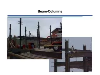
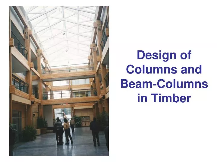
Design of Columns and Beam-Columns in Timber. Column failures. Material failure (crushing) Elastic buckling (Euler) Inelastic buckling (combination of buckling and material failure). P. L eff. Δ. P. Truss compression members Fraser Bridge, Quesnel. Column behaviour.

E N D
Column failures • Material failure (crushing) • Elastic buckling (Euler) • Inelastic buckling (combination of buckling and material failure) P Leff Δ P
Truss compression members Fraser Bridge, Quesnel
Column behaviour Perfectly straight and elastic column Pcr P Crooked elastic column Leff Δ Axial load P (kN) Crooked column with material failure P Displacement Δ (mm)
Pin-ended struts Shadbolt Centre, Burnaby
Column design equation P axis of buckling Pr = Fc A KZc KC where = 0.8 and Fc = fc (KD KH KSc KT) size factor KZc = 6.3 (dL)-0.13≤ 1.3 d L
Glulam arches and cross-bracing UNBC, Prince George, BC
material failure Capacity of a column FcA Pr combination of material failure and buckling π2EI/L2 (Euler equation) elastic buckling Le
Pin-ended columns in restroom building North Cascades Highway, WA Non-prismatic round columns Actual pin connections
Column buckling factor KC 1.0 KC limit 0.15 CC = Le/d 50
What is an acceptable l/d ratio ?? Clustered columns Forest Sciences Centre, UBC L/d ration of individual columns ~ 30
P P P P P P P P P P Effective lengthLeff = length of half sine-wave = k L Le Le Le Le * Sway cases should be treated with frame stability approach
Glulam and steel trusses Velodrome, Bordeaux, France All end connections are assumed to be pin-ended
Pin connected column base Note: water damage
Ley Lex Effective length
Partially braced columns in a post-and-beam structure FERIC Building, Vancouver, BC
Le Ley Lex L/d ratios y y x x y y d dx dy
Stud wall axis of buckling d L ignore sheathing contribution when calculating stud wall resistance
Fixed or pinned connection ? Note: bearing block from hard wood
An interesting connection between column and truss (combined steel and glulam truss)
Slightly over-designed truss member (Architectural features)
P P P P P P P P P P Effective length (sway cases)Leff = length of half sine-wave = k L Le Le Le Le Note: Sway cases should only be designed this way when all the columns are equally loaded and all columns contribute equally to the lateral sway resistance of a building
Sway permitted columns ….or aren’t they ??
Haunched columns UNBC, Prince George, BC
Frame stability • Columns carry axial forces from gravity loads • Effective length based on sway-prevented case • Sway effects included in applied moments • When no applied moments, assume frame to be out-of-plumb by 0.5% drift • Applied horizontal forces (wind, earthquake) get amplified • Design as beam-column
Note: This column does not contribute to the stability of the frame Frame stability(P- Δ effects) Htotal = H = amplification factor H = applied hor. load W H Δ h Δ = 1st order displacement
Minimal bracing, combined with roof diaphragm in lateral direction Haunched frame in longitudinal direction Sway frame for a small covered road bridge
Combined stresses Bi-axial bending Bending and compression
Heavy timber trusses Abbotsford arena
Pf fa = Pf / A neutral axis x fbx = Mfx / Sx Mfx x y fby = Mfy / Sy Mfy y fmax = fa + fbx + fby < fdes ( Pf / A ) + ( Mfx /Sx ) + ( Mfy / Sy ) < fdes (Pf / Afdes) + (Mfx /Sxfdes) + (Mfy / Syfdes) < 1.0 (Pf / Pr) + (Mfx /Mr) + ( Mfy / Mr) < 1.0 The only fly in the pie is that fdes is not the same for the three cases
Moment amplification P Δo Δmax PE = Euler load P
Interaction equation Axial load Bending about x-axis Bending about y-axis
wall and top plate help to distribute loads into studs joists top plate wall plate d L studs sill plate check compression perp.