Download
1 / 51
510 likes | 618 Views
Acoustic and Psychoacoustic issues in Room Correction. James D. (jj) Johnston Serge Smirnov Microsoft Corporation. This talk is in two parts:. First, JJ will discuss some basic acoustics, some psychoacoustic issues, and explain how that impacts the idea of room correction.

E N D
Acoustic and Psychoacoustic issues in Room Correction James D. (jj) Johnston Serge Smirnov Microsoft Corporation
This talk is in two parts: • First, JJ will discuss some basic acoustics, some psychoacoustic issues, and explain how that impacts the idea of room correction. • Then, Serge will explain how we actually implement these principles in the Vista™ room correction algorithm.
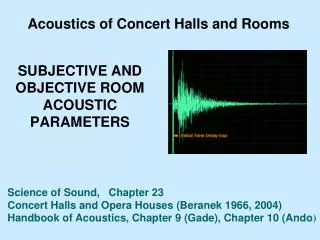
Acoustics- What does a room do? Diffuse tail Direct signal Early Reflections Unpleasantly large Late reflection Early reflections are those more or less under the 10 msec mark. “late” (specular) reflections create a problem with perception, more on that later. The example here is egregious.
What else does a room do? • That diffuse field • It is not frequency-flat • Almost always, high frequencies roll off much faster (lower t60) than lower frequencies. • It is (mostly) uncorrelated at the two ears, even taking into account ITD’s
A point to recall: • Because high frequencies decay faster than low frequencies (even on a cold, dry day in the desert): • If you measure the early arrival frequency response, it will show a different frequency balance than that of the entire tail • If you compare the early and late responses, the difference will be even bigger. • We’re used to listening to things that way, too, because it’s what we grow up with.
And a loudspeaker • Radiation patterns of loudspeakers are quite different at different frequencies • Typically, there is little directivity at bass frequencies • As frequency goes up, there is more directivity. • Many (consumer) speakers have fairly narrow high-frequency radiation patterns
So, what does that mean? • Many speakers, both consumer and professional, are not “power flat” in terms of polar response. • The total radiation from the speaker, not the front radiation, is what is added to the reverberant field. • This means that the reverberant field almost always gets proportionally less energy injected at high frequencies than low.
Well, now we combine the two • Several things happen • Due to both the lower t60 at higher frequency and the radiation pattern of the loudspeaker there is less energy in the diffuse field at high frequencies. • So, what do we equalize? First arrival at high frequencies or the whole thing? • What happens if we get that wrong? • There is a first-arrival • There may be a delayed reflection of a first arrival. • There are a variety of early reflections
So, we equalize what? • The long-term frequency response? • The short-term frequency response? • Some combination of both? • How “exactly” do we equalize the frequency response • How important is inter-channel matching Vs • Flattening all responses?
Some other acoustical issues • What do we measure? • If we use an omni, we record only pressure. • There are also 3 other variables at the same point, the volume velocities in each of X, Y, Z • If we use a cardioid, we record one combination of volume velocity and pressure • Specifically, we record half of the volume velocity in the direction of the microphone plus • Half of the pressure at the front of the microphone
So what do we correct? • Good question Some things to remember: • The eardrum converts PRESSURE into mechanical movement • The head, to some extent, converts velocity to pressure at the ear canal • Our head affects the “measurement” when it’s there listening.
Even more acoustical issues • Sharp zeros in frequency response • This does not mean signal is absent. • It means that there is no PRESSURE (presuming omni measurement mike) at the point in question • It means that volume velocity is at a peak at that point • The ENERGY in the room is there, but it’s in the (mostly) wrong form for the ear at THAT POINT IN THE ROOM. • Adding more energy, therefore, is not a very good solution. • The only time a zero is not a room storage issue is when the loudspeaker has a zero at that frequency • So fix it, already! • Once more, with feeling: adding more energy to the room while it’s storing energy at that frequency is not a solution!
Finally, a note about speakers and linear systems • Speakers are not linear devices • Speakers really aren’t linear devices • Speakers, in fact, are rather far from anything approximating a linear device. • So, it is a good idea to keep the energy at any one frequency low. • Sweeps don’t do that • Allpass sequences spread out the energy at any one frequency across time. This is “a good thing”.
NOW WHAT? • No, don’t abandon ship, the water is only up to your beltline!
What do the ears care about? • With the ear, both monaurally and binaurally FIRST ARRIVAL rules. • The “precedence” effect, which goes by any number of other names, shows that arrivals on the cochlea just after an attack are masked, even if they are quite a bit larger. • They do contribute to overall timbre • This means that most really early arrivals are masked
Ear Continued • The first-arrival provides a very strong localization effect binaurally. • This localization applies to anything that is correlated at the two ears, including with ITD range delays. • Signals that are not correlated at the two ears are not localized, and are, rather, heard as “envelopment”
Localization vs. Intensity • After the time cues are considered, intensity provides us with a variety of spatial cues • First, HRTF’s provide a variety of front/back, up/down cues. • Mismatched intensity at the two ears at higher frequencies moves the stereo image. • Remember, though, first arrival rules.
Remember: Specular reflections are correlated at the two ears. • The diffuse tail is not. • Some rooms are far, far, far from satisfactorily diffuse, hence “flutter echo” and like problems. This is not an easy problem to fix. • In the diffuse tail, bass hangs over much more strongly than high frequencies, both initially (due to loudspeaker radiation pattern) and more so later, due to lossy transmission and reflection of sound.
Diffuse perception • Signals that are not correlated (either by waveform at low frequencies or envelope at high frequencies) at the two ears are heard as “diffuse” or “surrounding”. • This means that we hear the diffuse response of the room as a different (set of) auditory objects than the direct sounds. • We are USED to the diffuse sounds being heavily colored in timbre.
Low frequencies • We live, day in and day out, in environments that provide a huge variation in the low-frequency environment. • We’re used to it • Nonetheless, huge excursions, especially peaks, are very annoying. • Again, remember the rule “don’t add energy if there’s already too much stored”.
So, the message is? • Equalize the direct arrival at high frequencies. • Since we are also used to hearing bumps and dips at low frequencies • Equalize the overall frequency response at low frequencies, don’t invert the whole thing • Whatever you do, don’t try to completely invert the system, i.e. correct both phase and magnitude.
Why not? • First, what are you inverting? Pressure? Volume velocity? Some of each? Does it relate to what your head/ear does in the soundfield? (Hint: NO ) • Second, if you try to invert phase, you’ll introduce pre-echo unless your fit and inversion are good to 60dB. • Even if it was when you did it, it won’t be when you exhale and change the humidity in front of your head.
What matters most to the ear? • First arrival timbre • Large peaks should be equalized • Large, sharp dips are not to be touched, remember the energy storage issue • Broad dips can be equalized out for a broader listening area
Where are we? • Obviously, you need to equalize • Gain from each speaker • Delay from each speaker • Frequency response, but within limits • But in what way? • Exact? • Relative? • Try to cancel, to some extent, that single first later reflection, but only at low frequencies.
Why only at low frequencies? • As the listener moves, the mic moves, etc, that delay will change • If you equalize at high frequencies, a mic in the center of your head will be wrong for both ears. • If you equalize only below 500Hz or so, you get a .5 foot radius space, give or take, where the cancellation makes some sense. • You only do SOME cancellation. Even some cancellation removes the “boxiness”, and does not provide a bizarre experience out of the sweet spot.
The practical outcome • At low frequencies, you’re adjusting the overall response of the room, not the details. • At high frequencies, you’re concerned only with the direct signal and the early reflections. This is almost “speaker plus speaker stand” correction • In any case, you correct whatever’s most egregious, speaker, room, whatever. • Fix what you can, and don’t touch the rest.
Relative vs. Flat correction • Relative correction • Reduces the image shift and spread • Fixes first arrival (time, frequency response, gain) cues in the soundfield • Does not require a calibrated microphone • Provides very good stereo imaging • Flattening each channel individually • Requires a calibrated microphone • Does not assure channel matching, in fact, the “best” flattening solution for each speaker will not in general assure best relative match • Fixes first arrival cues for gain and time just like relative systems • Does provide the measurably “flattest” response
Relative or Flat • Flat costs more for equipment • Flat requires more CPU if done “accurately” • Flat doesn’t fix imaging as well, unless relative is also added, in which case you need even more CPU • Relative is cheaper, both in equipment and CPU • Relative corrects the most obvious defects.
First Reflection Cancellation • This is an individual adjustment for each channel • It removes the “boxy” sound to some extent • Fixing this for the listening location means that we do put more impairments elsewhere in the room. • Can be adjusted to avoid obvious impairments and still have some productive effect. • Can clean up “boom” to some extent as well.
Conclusions: • At low frequencies, correct the overall room response • At high frequencies, correct the first arrival • Always, obviously, correct gain and delay between channels • Relative correction between channels does more perceptually than the same amount of CPU applied to flattening the system analytically. • Too much correction is bad • Long-window corrections at high frequencies cause the “dentist drill” experience, because the system will be equalized to provide way, way too much correction at high frequencies for the first-arrival signal.
After the break: • Serge Smirnov tells us • How to implement a room correction that addresses the perceptual issues • How to keep the CPU load down at the same time
The Break • We’ll do door prizes after the break • Please take a 15 minute stretch.
Sequence of operations • Generate probe signals • Measure delays • Measure gains • Measure frequency response • Identify first reflection • (delays are measured from one set of captures, the rest are measured from a second set of captures)
Probe generation • Synthesized in Frequency (Discrete Fourier) domain: • Magnitude the same at all frequencies * • Phase is continuous across frequency including at pi and zero • Extent of time spread is limited by phase change, no window necessary • DFT values at a negative and positive frequencies are complex conjugates to generate real signal • Transformed to time domain using inverse complex FFT • Imaginary part of complex time domain signal is zero • Real part of complex time domain signal is the probe signal *but see next slide
Narrowband vs. Wideband Probe • We actually generate two probes • The wideband probe used for identifying the system impulse response • A narrowband probe used as a matched filter to capture time and delay, while rejecting low and high frequency interference (noise)
Characteristics of the Probe Signal Autocorrelation Time Domain Spectrum Unwrapped phase
Cross-channel delay probing • silence between probes (for room to settle) • extra marker probe at the end to detect timing glitches in audio capture/playback • LS/RS could be LR/RR • Can also do 7-channel or other arrangement, using same method
Capture from mic for delay probing Can you find the pulses?
Delay analysis – Hilbert (aka Analytic) envelope What comes out Probe Autocorrelation Note the noise rejection
Gain, Freq response, etc. measurements (this happens for each channel separately) N takes are used for wide probe in case sporadic room noises interfere
Gain analysis (per channel, per take) Gain is derived from the 800-2000Hz average of power spectrum coefficients Only the first N (128) samples of the impulse response are used Then, for each channel, throw away outliers and average the rest Finally, normalize all gains relative to the channel with the highest/lowest gain Reject the results if there is too much variation
Frequency domain deconvolution • Power spectrum of captured signal • Power spectrum of captured signal complex-divided by FFT of probe • First 400 samples of IFFT ( FFT ( capture ) / FFT ( probe ) )
Frequency response analysis (per channel, per take) Deconvolution by way of division in the frequency domain Then, for each channel, throw away outliers and average the rest Finally, if relative response correction is specified, normalize all responses relative to the average of all channels
Computation of FIR correction filter (with apologies) • Separate correction filters are computed for low vs high frequencies • Each filter assumes that the part it doesn’t do is flat • Durbin LPC is used to obtain all-zero inverse filters (normally Durbin LPC is used to obtain all-pole direct filters) • transition between the low high is done in log(power spectrum) domain • Low- and high-freq correction filters are convolved to obtain final filter • final filter is then (not shown) normalized for unity avg gain 800-2000Hz
Location of First reflection • Computed from analytic envelope
Denominator of all-pole reflection cancellation filter • Reflection correction filter has a trivial numerator (“1”) • Denominator uses (upside down) the coefficients of a specially crafted M-tap symmetric low-pass FIR positioned at a distance determined by reflection delay. I.e., it recursively subtracts LP-filtered version of echo.
The Low Pass filter • Provides a wider “sweet spot” • Avoids “flutter echo” problems off-axis • Ensures 100.00% filter stability • The data for the filter is internal to the rendering engine • The stored information is only gain and delay, which can be trivially tested for stability at startup time
The Rendering Engine • applies per-channel gain, delay, FIR filter (frequency response correction), IIR filter (reflection cancellation) • Is low complexity in CPU, RAM, ROM • Allows application of a “partial profile” (say to 2 channels of a 7.1 profile) • Allows limited application of a profile generated for a different sample rate