Download
1 / 22
291 likes | 1.11k Views
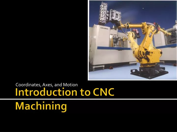
Coordinates, Axes, and Motion. Introduction to CNC Machining. Overview. We’ll first learn about axis systems. Then we’ll investigate how the machines understand where to move, and the kinds of moves they can make getting there. . World Axis Standards.

E N D
Coordinates, Axes, and Motion Introduction to CNC Machining
Overview • We’ll first learn about axis systems. • Then we’ll investigate how the machines understand where to move, • and the kinds of moves they can make getting there. Machining and CNC Technology by McGraw-Hill Higher Education
World Axis Standards Unless it’s a multiplexed machine with several auxiliary rotary and linear axes, these nine are adequate to define most of the equipment in industry today. However, for tomorrow’s manufacturing world, that’s another question? Machines continue to evolve as central processors are able to handle more and more calculations per nanosecond, thus more functions simultaneously. • There are 14 standard axes defined by the Electronics Industries Association (EIA) used for motion and position. • In this course we’ll study 9 of them. • 3 Primary Linear Axes X, Y and Z • 3 Primary Rotary Axes A, B and C • 3 Secondary Linear Axes U,V and W Machining and CNC Technology by McGraw-Hill Higher Education
Identifying Machine Axes • Whenever you are assigned to a new CNC machine, the axis set must be identified as the first order of business. • Here are the sets for three common machines. Machining and CNC Technology by McGraw-Hill Higher Education
Quick Tips on Axis ID • It’s easy to identify the spindle, which is the Z axis or it faces Z. • Then apply the Right Hand Rule by pointing your right middle finger in the positive Z direction. • Your fingers and thumb then form the orthogonal axis frame (mutually at 90º) Machining and CNC Technology by McGraw-Hill Higher Education
The Right Hand Rule • First identify the Z axis. It’s parallel to the spindle axis, and brings the work toward and away from the spindle. • Pointing your middle finger in the positive Z direction, your index finger and thumb form the other positive axes. Machining and CNC Technology by McGraw-Hill Higher Education
Orthogonal but not always level The set (my fingers) remain in the same orientation to each other no matter their world orientation • All CNC machines use the X-Z or X-Y-Z frame, with each axis perpendicular to the others. • That relationship stays the same no matter how the axis set is rotated to suit the machine. • Toward stronger or more efficient machines manufacturers arrange the set any way convenient, but not the inter-relationship between axes. Machining and CNC Technology by McGraw-Hill Higher Education
Now a serious example: A slant-bed lathe • The X axis on many turning centers, is not parallel to the floor, it slants forward. • That provides easy access to the turret for setup work, since the machine isn’t as wide as level X axis machines. • Plus chips and coolants slide right off to the catch basin below. X Slanted Z 90º This lathe’s world axis orientation is not level but it’s still an orthogonal set. Machining and CNC Technology by McGraw-Hill Higher Education
Primary Rotary Axes A,B & C • Whenever a machine features a rotary axis, we identify it this way: • If it rotates around a line parallel to X it’s an A axis Y it’s B Z it’s C Machining and CNC Technology by McGraw-Hill Higher Education
Rotate Cutter or Part • Rotary axes can move a cutter head in an arc • Or they can move the workpiece in an arc. • In this film we see A and B auxiliary axes moving simultaneously with X, Y and Z, to cut this complex turbine blade. Machining and CNC Technology by McGraw-Hill Higher Education
Which Direction? • To determine the direction of rotary motion, either plus or minus A,B or C, we use the Rule of Thumb. • It’s based on the line about which the rotary axis pivots, X, Y or Z Point the thumb of your right hand in the direction of the rotary axis’ line of rotation, X, Y or Z positive direction. X+ Z+ Y+ Positive C direction Positive A direction Positive B What motion? Machining and CNC Technology by McGraw-Hill Higher Education
Absolute Value Coordinates • In CNC work, the origin, X0, Y0, Z0, is known as the Program Reference Zero (PRZ) • It’s the starting point for coordinates • Most coordinates in the program refer their distance from the PRZ. • For example. The tip of the drill is at X2.500, Y1.00, Z-1.00 Relative to the PRZ which is the lower left corner on this part Machining and CNC Technology by McGraw-Hill Higher Education
Incremental Value Coordinates • Occasionally we encounter the need for a different kind of coordinate. • They do not refer to the PRZ but rather, to their last position. • Incremental coordinates are jumps from where you are to where you wish to go next. Machining and CNC Technology by McGraw-Hill Higher Education
CNC Motions • CNC machines move their axes in five ways: Rapid Travel Linear single or multi axis straight line motion Circular motion within a single plane. Circular/Linear, also called 2 ½ dim. motion. Two axes move in an arc while the third moves in a straight line. 3-D motion few controls have the ability to move in an arc using 3 axes simultaneously. Most approximate these arcs through the power of the cam software. Machining and CNC Technology by McGraw-Hill Higher Education
Rapid Motion Trade Tip Caution! Depending on the power of the CPU, your machine will rapid in one of two ways. Older controllers take an unexpected nonlinear path! Newer controllers with 16-bit or higher microprocessors follow the true linear motion. Rapid – as fast as the machine can move but with the ability to reduce speed through operator over-ride control. Machining and CNC Technology by McGraw-Hill Higher Education
Feed Rate Motions • The next four motions all move one or more axes at the rate specified in the program. • The differences lies in how many axes are involved, in a straight line, or arc. • As motions become more complex, the CPU must handle far more calculations per second by interpolating each axes drive commands. Machining and CNC Technology by McGraw-Hill Higher Education
Interpolating • To move axes simultaneously, to produce a constant velocity along the line A-B, say at 400 inches per minute. • neither the X or Y axis will be moving at 400 IPM. • They will run at lower speeds that combine to create the tool motion of 400 IPM. Machining and CNC Technology by McGraw-Hill Higher Education
Linear Interpolation Point A to B B Programmed Rate 400 Inches Per Minute 137.81 IPM Y Axis A 375.87 IPM, X Axis Motion Machining and CNC Technology by McGraw-Hill Higher Education
Feed Rate Over-ride • The linear interpolation required the control to set each axis moving at constant values but different rates. • The operator can over-ride the resultant tool motion from 0% (no movement) up to 100% or 150% on some machines. Machining and CNC Technology by McGraw-Hill Higher Education
Circular and Above • For arc motion at feed rate, the controller is also interpolating as with linear. • The difference is it is constantly changing the ratio between the axes involved, as the curvature changes slants. Machining and CNC Technology by McGraw-Hill Higher Education
Polar Coordinates Trade Tip Using polar coordinates, often saves a trigonometry step during drawing or hand program writing! If the needed significant point is defined in radius-angle, rather than X-Y, why do an unnecessary calculation? Define it with an R-A coordinate on your geometry drawing. • Sometimes engineering information comes not in the form of rectangular dimensions, but rather as the radius and angle from a starting point. • Those points are more easily defined using polar coordinates – a bolt circle for example. • Polar Coordinates aren’t used inside CAM generated programs, but they are very useful for drawing the part geometry or when doing hand program writing of polar entities. Machining and CNC Technology by McGraw-Hill Higher Education
Next Assignment • Mastercam X2Beginner Training Tutorials • Review Exercise 1, in Tutorial 2 • Review Exercise 2, in Tutorial 3 • Email Subject Line • LastnameMill2&3 • Only attach Zip2Go files for each part