Download
1 / 40
450 likes | 1.45k Views
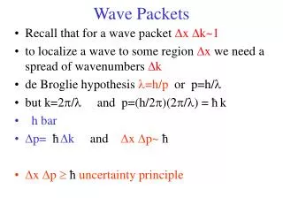
Choke Packets. Used for congestion control (both VC & datagram nets) Router monitors utilization of output lines If a threshold is passed, set a warning state for the line

E N D
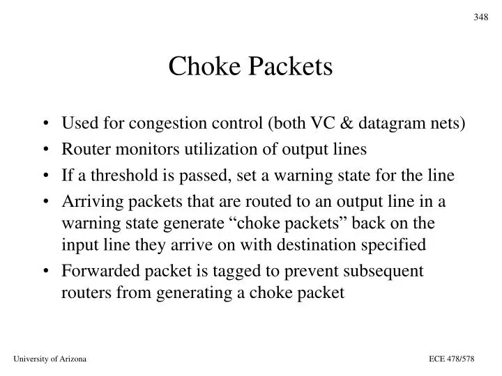
Choke Packets • Used for congestion control (both VC & datagram nets) • Router monitors utilization of output lines • If a threshold is passed, set a warning state for the line • Arriving packets that are routed to an output line in a warning state generate “choke packets” back on the input line they arrive on with destination specified • Forwarded packet is tagged to prevent subsequent routers from generating a choke packet ECE 478/578
Choke Packets (Cont.) • Source host receiving choke packet must reduce rate of traffic sent to the specified destination • Since packets in transit may generate several choke packets, a host can ignore choke packets for a fixed time interval after receiving the first one • After the interval if there is still a congestion problem, the host well get more choke packets and must then reduce its rate further ECE 478/578
Choke Packets (Cont.) • Since this technique is feedback driven, it doesn’t slow the flow when there is no congestion • Variations include multiple warning levels and different forms of utilization (# buffers used, queue length) as trigger • PROBLEM: what if offending host ignores the choke packets? ECE 478/578
Hop-by-Hop Choke Packets • Choke packet takes too long to get back to source in large WAN with high-speed source reacts slowly • This algorithm has the choke packet affect each hop (usually a router) along the path • The goal is to address congestion quickly at the point of greatest need propagate the “relief” back to the source ECE 478/578
Hop-by-hop Choke Packets (Cont.) • This generates greater need for buffers at the router • Required to reduce output • Meanwhile the input continues full blast until the choke packet propagates to the next hop ECE 478/578
Load Shedding • The “big hammer” - router just starts throwing out packets • Packet discard policy may depend on the application • “wine” drop new packets (old wine is better than new wine) - good for file transfer • “milk” drop old packets (don’t even need to talk about old milk!) - good for video/multimedia ECE 478/578
Load Shedding (Cont.) • Requires application to mark packet with priority • How to keep every packet from being marked - DO NOT DISCARD ? • Back to carrier/customer environment - make it cheaper to send LOW PRIORITY packets ECE 478/578
Load Shedding (Cont.) • If service is negotiated mark, any packets that exceeded the negotiated service as low priority • For most networks a packet may be just a portion of a message (48 byte payload of ATM cell is usually a piece of a PDU) and dropping a cell will usually result in retransmission of whole PDU • Drop all the cells making up that PDU • Use early packet discard to try to preempt congestion ECE 478/578
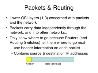
Internetworking Issues • Expect that there will continue to be a large variety of protocols at each layer • Interconnecting heterogeneous networks will introduce many conflicts • To provide services we want the network layer to accommodate: • Different addressing schemes • Different maximum packet sizes • Different network access mechanisms ECE 478/578
Connection oriented Internetwork H1 S S S H2 M S S S S H2 G G H1 R R G Internetworking Approaches Connectionless Internetwork ECE 478/578
Internetworking Issues • Network layer may have to accommodate: • Different timeout values • Error recovery • Status reporting • Routing & congestion control • User access control • Service philosophy ECE 478/578
Internetworking Approaches • Same two competing approaches: • Connection oriented with virtual circuits • Connectionless with Datagrams ECE 478/578
H1 S S S H2 M S S S S Connection Oriented Approach • We build a virtual circuit pathway through the internetwork between the source and the destination • Switches maintain information about VCs ECE 478/578
Connection Oriented Approach (Cont.) • The connection-oriented approach is often more appropriate when the internetwork is homogeneous • Benefits of VC based internetworking: • Resource allocation at circuit setup • Sequencing is guaranteed • Low header overhead • No duplicate packets ECE 478/578
Connection Oriented Approach (Cont.) • Drawbacks: • Switch resources needed for each circuit • Switch failure brings down the whole connection • Certain paths may be susceptible to congestion • Difficult to incorporate non-VC based network into the internetwork ECE 478/578
H2 G G H1 R R G Connectionless Internetwork Connectionless Approach • For connectionless we route the packets through the network with routers performing a role similar to the switches but packets do not need to all follow the same route • Useful for heterogeneous networks ECE 478/578
Gateways • Gateways interconnect networks with different naming/addressing conventions, depending on layer: • Repeaters - physical layer • Bridges - DL/MAC layer • Routers (gateways, Multiprotocol routers) - network layer • Transport gateways - transport layer • Application gateways (e.g. email gateway) - application layer ECE 478/578
Example: Network Gateways • Here, the gateway performs routing and translation functions between Network A and Network B Network A Network B HOST HOST ECE 478/578
Tunneling • Gateway does not translate to the WAN protocol between Network A and Network B but wraps the IP packet in a WAN packet and sends it transparently (tunnels) across the WAN. A & B seem to have a direct serial link. Network B Network A HOST HOST WAN ECE 478/578
Fragmentation • If data has to traverse many diverse networks, it is likely that they will have different maximum data “payload” sizes • This may be determined by the operating system parameters, protocol specifications, etc. • Usually the size of PDU payload increases in higher layers (higher levels of abstraction) • Internetwork has to deal with differences - usually means we have to fragment larger packets ECE 478/578
Fragmentation (Cont.) • Easy part - Gateway is allowed to break up a packet into fragments and send fragments separately • Hard part - Gateway has to put pieces back together to reconstruct the original packet • So the obvious question is - do we need to put them back together again? • As usual there are two competing viewpoints • Transparent Fragmentation • Non-Transparent Fragmentation ECE 478/578
H1 R1 G1 R2 G2 R3 R1 H1 G7 G8 Transparent Fragmentation • Fragments recombined at each gateway and original sized packet delivered at destination • Requires all packets to leave network via same gateway some performance loss • Gateway needs to know when all fragments are received ECE 478/578
H1 G1 G2 G3 G4 G5 G6 H1 G7 G8 Non-transparent Fragmentation • Do not recombine fragments at each intermediate gateway each fragment becomes an independent packet • Allows fragments to take separate paths • Recombination takes place at the destination host ECE 478/578
The Internet Protocol (IP) • A collection of Autonomous Systems interconnected by one or more backbones • Loose, collaborative structure with Autonomous Systems (AS’s) organized into Regional Networks interconnected into the larger Internet • Developed from DARPANET NSFNET Internet • Provides best effort datagram service to Transport Layer ECE 478/578
IP Packet Header Format 0 4 8 16 19 24 32 Bits VER Type of Service Total Length IHL FLAGS Fragment Offset Identification Protocol Header Checksum TTL Source IP Address Destination IP Address Option Parameters (0 or more 32-bit words) ECE 478/578
Basic IP Services • Send and Receive services • Send (Src Addr, Dst Addr, Protocol, Service Type, Identifier, Don’t Fragment, TTL, Len, Options, Data) • Src Addr = IP Address of sender • Dst Addr = IP Address of destination • Protocol = Recipient Protocol using IP Services • Service Type = Indicates type of service requested • Identifier = Combined with three above to uniquely identify data unit ... ECE 478/578
Basic IP Services – Send (Cont.) • Don’t Fragment = Says whether or not IP is allowed to fragment data • TTL = Time To Live for packet • Len = Length of data being sent • Options = Options requested by IP user • Data = The IP user data ECE 478/578
Options • Allow rarely used parameters and future extensions • Security • Source routing (specify list of routers for packet) • Route recording (keep a record of routers visited by packet) • Stream ID • Timestamping (source and intermediate routers timestamp packet) ECE 478/578
IP Addressing 32 Bits 0 8 16 24 Host Class A Network 0 Host Network Class B 1 0 Host Network Class C 1 1 0 Multicast Address Class D 1 1 1 0 Reserved 1 1 1 1 0 Class E ECE 478/578
IP Addressing - Special Addresses This host 0 0 0 0 0 0 …………………….. 0 0 0 Host on this Network 0 0 0 0 ……. 0 0 Host Broadcast on this Network 1 1 1 1 1 1 1 …………………….. 1 1 1 Broadcast on remote Network NETWORK 1 1 1 1 1 . . . . . 1 1 1 127 Loopback DON’T CARE ECE 478/578
Internet Control Message Protocol (ICMP) • IP standards specify that compliant implementations must also implement ICMP (RFC 792) • ICMP provides a mechanism to provide feedback about problems in the network • ICMP packets can be sent by routers and hosts • ICMP exists at the NL but is a user of NL services, i.e., it uses IP datagram service • ICMP packets are usually generated by a host or router in response to a previous datagram ECE 478/578
ICMP (Cont.) • ICMP packets have a 64-bit header which includes: • Type (8 bits) - type of ICMP packet • Code (8 bits) - specifies parameters of the packet • Checksum (16 bits) - checksum for entire ICMP packet • Parameters (32 bits) - parameters too large for Code • Header is usually followed by additional information depending on packet type • When the packet refers to a previous datagram the additional info includes the IP header and first 64 bits of the original datagram ECE 478/578
Types of ICMP Packets • Inclusion of first 64 bits of data after the IP header is to allow IP entity to determine which IP user was associated with the datagram • Types of packets include: • Destination unreachable (e.g., router can’t reach destination network) • Time exceeded - TTL of datagram reached zero • Parameter error - semantic error in IP header • Source quench - simple flow control ECE 478/578
Types of ICMP Packets (Cont.) • Redirect - advise host of a better route • Echo (reply) - test communications • Timestamp (reply) - allow determination of delay • Address mask req (reply) - inform host of LAN’s subnet mask ECE 478/578
Type Code Checksum Type Code Checksum Unused Identifier Sequence # Originate timestamp Type Code Checksum Type Code Checksum Ptr Unused Identifier Sequence # IP Header + 64 bits original dg Originate timestamp Receive timestamp Transmit timestamp Some ICMP Packet Formats Dst. unreachable, time exceeded, src quench Timestamp Parameter error Timestamp reply ECE 478/578
Type Code Checksum Type Code Checksum Gateway IP Address Identifier Sequence # IP Header + 64 bits original dg Address mask request Redirect Type Code Checksum Type Code Checksum Identifier Sequence # Identifier Sequence # IP Header + 64 bits original dg Address Mask Some ICMP Packet Formats (Cont.) Echo, Echo Reply Address mask reply ECE 478/578
Mapping IP to DL Addresses • Consider IP layer running on an IEEE 802.3 LAN • Recall DL has its own 48-bit addresses • NL superimposes an internetwork on top of the LAN and provides its own 32-bit IP address space • DL knows nothing about IP addresses • How do these two sets of addresses get mapped to each other? ECE 478/578
Address Resolution Protocol (ARP) • Another control protocol which resides at the NL • ARP builds a DL broadcast frame with a packet “what’s the DL address for IP address w.x.y.z?” and sends it • Broadcast frame is received by all hosts and one says “that’s me!” or another says “I know” ECE 478/578
Address Resolution Protocol (ARP) • Host recognizing the IP address builds a response giving the DL address to IP address mapping and sends it to the sender of the broadcast • Address mappings are cached to prevent repeated broadcasts • DL-to-IP mapping of sender may be cached by all hosts on the LAN for future use ECE 478/578
Address Resolution Protocol (ARP) • Host may broadcast ARP for its own address upon booting as a way of announcing its mapping • This is a simple and effective protocol which eliminates need for maintaining static tables • Since LAN broadcasts are not routed, the router DL generally becomes the mapping for remote networks ECE 478/578