Download
1 / 35
350 likes | 694 Views
Electronic Instrumentation. Project 2 1. Optical Communications 2. Transmitter Circuit 3. Receiver Circuit 4. Signal Reconstruction 5. Project Report 6. Practical Questions. Optical Communications. Transmitting an audio signal using light. Transmitter Circuit. audio signal.

E N D
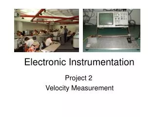
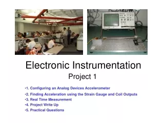
Electronic Instrumentation Project 2 1. Optical Communications 2. Transmitter Circuit 3. Receiver Circuit 4. Signal Reconstruction 5. Project Report 6. Practical Questions
Optical Communications ENGR-4300 Electronic Instrumentation
Transmitting an audio signal using light Transmitter Circuit audio signal Receiver Circuit ENGR-4300 Electronic Instrumentation
Modulation • Modulation is a way to encode an electromagnetic signal so that it can be transmitted and received. • A carrier signal (constant) is changed by the transmitter in some way based on the information to be sent. • The receiver then recreates the signal by looking at how the carrier was changed. ENGR-4300 Electronic Instrumentation
Amplitude Modulation http://cnyack.homestead.com/files/modulation/modam.htm ENGR-4300 Electronic Instrumentation
Frequency Modulation http://cnyack.homestead.com/files/modulation/modfm.htm ENGR-4300 Electronic Instrumentation
Pulse Width Modulation http://cnyack.homestead.com/files/modulation/modpwm.htm ENGR-4300 Electronic Instrumentation
Pulse Position Modulation http://cnyack.homestead.com/files/modulation/modppm.htm ENGR-4300 Electronic Instrumentation
Optoisolators • Optoisolators use light to transfer a signal between two devices rather than a direct electrical connection. • You can buy computer cards with optoisolating connectors that protect the computer from devices connected to it. Good for industrial applications. ENGR-4300 Electronic Instrumentation
Servo-motor control • The servo-motors are controlled by the computer through an optoisolating card. • The low voltage DC computer is protected (isolated) from the high voltage AC power needed to turn the motors. ENGR-4300 Electronic Instrumentation
Transmitter Circuit ENGR-4300 Electronic Instrumentation
555-Timer in Astable Mode ENGR-4300 Electronic Instrumentation
Input and Modulated Output ENGR-4300 Electronic Instrumentation
Special Capacitors DC Blocking Capacitor (High Pass Filter) Bypass Capacitor (Low Pass Filter) ENGR-4300 Electronic Instrumentation
Sample Input and Output • As input rises, pulses are longer • As input falls, pulses are shorter ENGR-4300 Electronic Instrumentation
Your signal is what? • Called pulse position modulation in .pdf file • Also looks like pulse frequency and pulse width modulation ENGR-4300 Electronic Instrumentation
Sampling Frequency • The pot (used as a variable resistor) controls your sampling frequency • Input frequency in audible range (0-4K Hz) • Sampling frequency should be between 8KHz and 48K Hz to reconstruct sound • Input amplitude should not exceed 1V ENGR-4300 Electronic Instrumentation
Receiver Circuit ENGR-4300 Electronic Instrumentation
Receive Light Signal ENGR-4300 Electronic Instrumentation
Inverting Amplifier (Pre-Amp) ENGR-4300 Electronic Instrumentation
Audio Amplifier ENGR-4300 Electronic Instrumentation
Audio Amplifier Details increases gain 10X (optional) 386 audio amplifier high pass filter volume low pass filter ENGR-4300 Electronic Instrumentation
Special Capacitors DC Blocking Capacitor Bypass Capacitor ENGR-4300 Electronic Instrumentation
Signal Reconstruction • The signal is reconstructed well enough by this design that it will be audible. • In order to improve the quality of the signal, you will add an integrator, which will more exactly reconstruct it. • Types of integrators • passive integrator (low pass filter) • active integrator (op amp integrator circuit) ENGR-4300 Electronic Instrumentation
Passive Integration Integration works only at high frequencies w >> wc. Unfortunately, your amplitude will also decrease. ENGR-4300 Electronic Instrumentation
Active Integration Integration does not work at frequencies below wc. Your gain goes from -Rf/Ri to -1/RiC ENGR-4300 Electronic Instrumentation
Signal Reconstruction • integration • pulse on = + slope • pulse off = -- slope • ratio determines rise and fall • design parameters • sampling frequency • type of integrator • integrator components ENGR-4300 Electronic Instrumentation
Comparing Output of Blocks • location of points A-H are indicated in the project write-up • function of each block you should be able to determine from these notes and the experiments • take two measurements at a time • A on channel 1 and B on channel 2 • B on channel 1 and C on channel 2 • take all measurements relative to ground ENGR-4300 Electronic Instrumentation
Project Report • Introduction • Application Goals • Educational Goals • Basic Design • Identify function of each block • Identify input frequency and amplitude • Circuit diagram • Circuit built and witnessed • Take data at specified points ENGR-4300 Electronic Instrumentation
Final Design • What type of integrator? • What components? • Calculations • Circuit Diagram • Testing Plan • Design Changes • Problems Encountered • Take data at specified points • Have changes improved audio quality? ENGR-4300 Electronic Instrumentation
Analysis and Comparison • Analyze each block • PSpice or hand analysis • Show calculations or explain plot output • Compare experimental with theoretical results • How are they different?... the same? • Why are they different? • Compare basic and final design • signal reconstruction • sound quality ENGR-4300 Electronic Instrumentation
Personal Responsibilities • Make a list of all tasks to be completed as part of this project • Testing plan • Keep everyone on task • Assign responsibility for each task to one person (tasks cannot be shared) • Have task assignment list checked out ENGR-4300 Electronic Instrumentation
Appendices • Useful data or results from experiments • Information resources • From the web • From the library or other sources • Only attach useful information • Useless information will result is a loss of points • Explain the purpose of each piece of info ENGR-4300 Electronic Instrumentation
Practical Questions The participation points for this project will be determined based on practical skills. To test practical skills, students will be asked to perform simple practical tasks related to this project in a timely fashion. The instructor or the TA will assign the points. Please notice that the practical questions are meant to be answered individually. ENGR-4300 Electronic Instrumentation
describe the goal and the methodology identify components and parts of each circuit debug the circuit connect the circuits to the power supply and to the ‘scope use PSpice traces and cursors. draw Capture circuit set up ‘scope to compare the output of two blocks set function generator to get a signal comparable to an audio signal capture the ‘scope signal both as a picture and data, using Agilent Intuilink adjust sampling frequency choose integrator component values Sample Practical Questions ENGR-4300 Electronic Instrumentation