Download
1 / 18
330 likes | 1.94k Views
Stepper Motors ME-191 Computer Applications in Mechanical Engineering II Dr. William Farrow Stepper Motor An output transducer that converts a digital signal to discrete rotational motion. Types of Stepper Motors Permanent Magnet Permanent Magnet Rotor (the part that rotates

E N D
Stepper Motors ME-191 Computer Applications in Mechanical Engineering II Dr. William Farrow
Stepper Motor • An output transducer that converts a digital signal to discrete rotational motion. ME-191 Computer Applications in Mechanical Engineering II
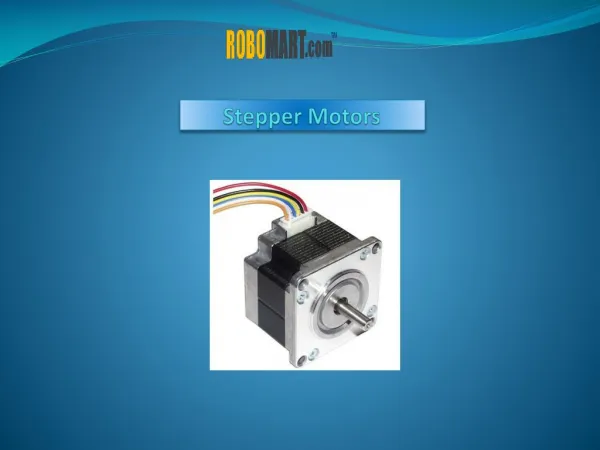
Types of Stepper Motors • Permanent Magnet • Permanent Magnet Rotor (the part that rotates • Smaller size, Faster possible speeds • Lower max torques • Variable Reluctance • Iron or Steel Rotor • Larger size, Slower possible speeds • Larger max torques ME-191 Computer Applications in Mechanical Engineering II
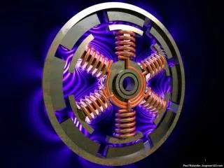
Permanent Magnet • Permanent magnet rotor’s magnetic field is driven around by attraction to and repulsion from electrically switched stator field coils (or poles). ME-191 Computer Applications in Mechanical Engineering II
Variable Reluctance • Steel rotor seeks position of minimum reluctance under influence of the electrically switched stator field coils (or poles). ME-191 Computer Applications in Mechanical Engineering II
Performance • Torque • PM limited to ~500 oz-in • VR limited to ~2000 oz-in • Speed • PM smaller rotor size higher speeds • VR larger rotor size smaller speeds ME-191 Computer Applications in Mechanical Engineering II
Performance • Input speed • Measured in steps/second • Some PM’s can reach 30,000 steps/sec • Resolution • Measured in steps/revolution • Commonly 12, 24,144, 180, 200, and 400 • Or from 30°/step down to 0.9°/step • Half-stepping can further enhance resolution ME-191 Computer Applications in Mechanical Engineering II
Important Parameters to Maintain Open Loop Control ME-191 Computer Applications in Mechanical Engineering II
In Addition: • VR – holding torque is zero when power is off • PM – holding torque is generated by PM field and steel stators (detent torque) ME-191 Computer Applications in Mechanical Engineering II
Typical Stepper Motor Characterics ME-191 Computer Applications in Mechanical Engineering II
Lab 3 XY Table • Apply the concept of stepper motors to drive a XY positioning table ME-191 Computer Applications in Mechanical Engineering II
XY Table Layout ME-191 Computer Applications in Mechanical Engineering II
Stepper Motor Driver • Digital logic used to command stepper motor • This lab applies the UCN5804 IC to control the stepper motor via digital outputs from the LabJack • MOSFET power switching transistors used to amplify power to the stepper motor pole coils ME-191 Computer Applications in Mechanical Engineering II
Stepping Signals • X-Axis step • D1 - direction • Low (0) or High (>0) opposite directions • D0 - move one step • High (>0) followed by a Low (0) • Note: requires two digital output calls • D8 & D9 - limit switches for travel • Inputs go high when switch is closed ME-191 Computer Applications in Mechanical Engineering II
Lab Operation • Connect hardware and test using LJLogger • Write m-file to move X-Axis 100 steps ME-191 Computer Applications in Mechanical Engineering II
Lab Operation cont. • Locate middle of Axis • Move x-axis until limit switch A is set • Will require While-loop and edigitalin() to monitor switch A • Reverse direction and count # of steps to B • Will require While-loop • Need to increment value in a variable steps • Reverse direction and move ½ the # steps • Require a For-loop to go ½ of steps ME-191 Computer Applications in Mechanical Engineering II